The greatest difficulty caused voeroesmarty pendulum mechanism. Of course, it would be possible to design a real pendulum that specifies the precision of the electronic clock, but to create such a complex device had no reason to, and I have developed a much simpler Electromechanical device that simulates the motion of the pendulum.
The pendulum consists of a rod made of polished duralumin tube with a diameter of 12×1 mm with suspension point on the line that divides it in the ratio 1:2. The hinge suspension is a steel bracket screwed into it with two M5 set screws with conical end portions. In the rod of the pendulum are drilled, respectively, two cylindrical holes with a diameter of 2 mm. At the bottom of the pendulum is fixed an ornamental disk and the load is first made of the CD and the second steel strip. If necessary, increasing or decreasing the load, it is possible to change the oscillation frequency of the pendulum.
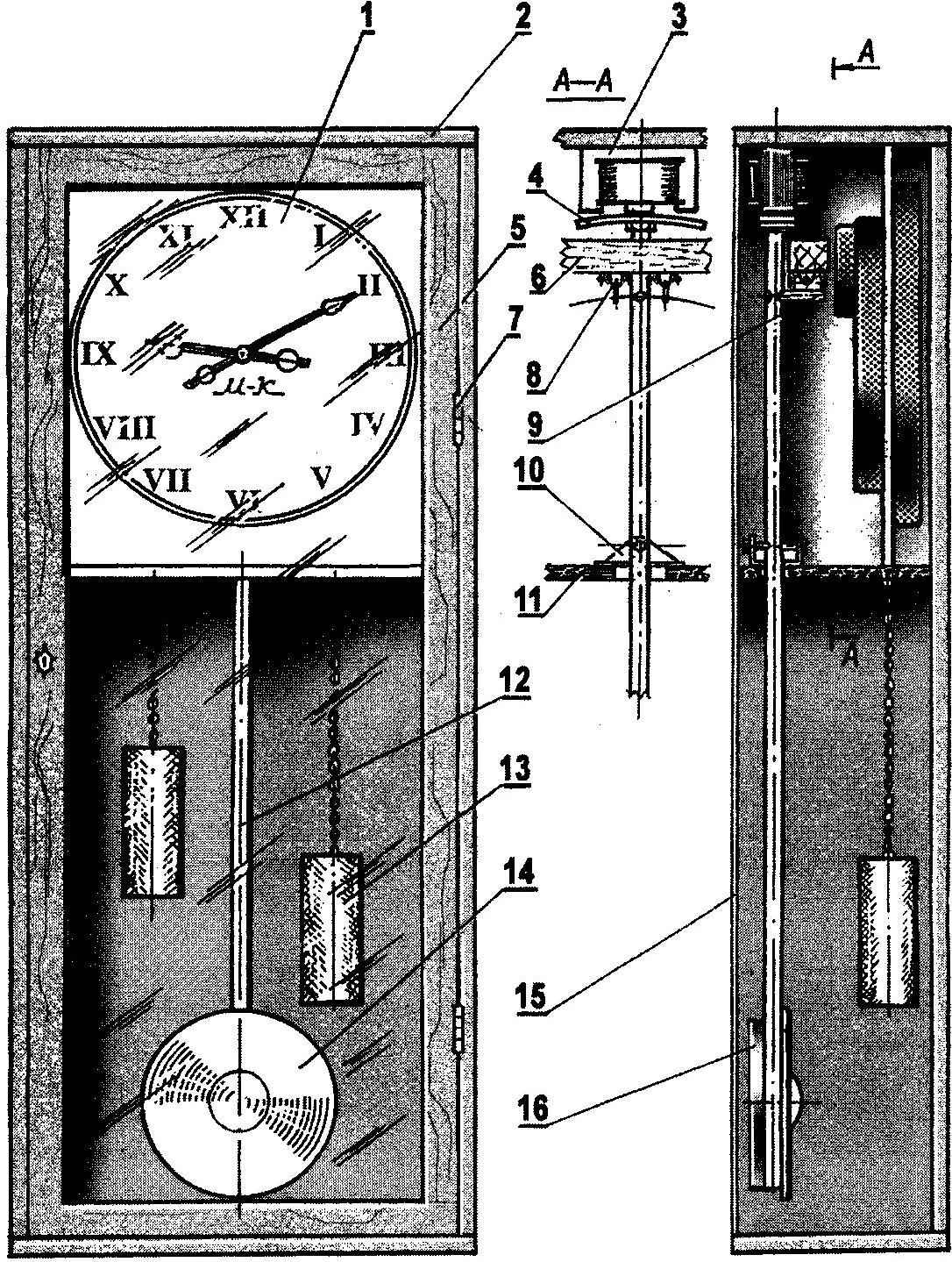
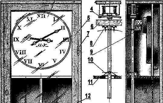
The device is homemade and old pendulum clock:
1—electronic clock; 2— body of the locker; 3—electromagnet; 4—anchor of the pendulum; 5—door locker; 6—jumper for mounting switches; 7—mesh; 8—pin petal switch; 9—contactor; 10—the hinge of the pendulum; 11—shelf for mounting electronic clock and pendulum; 12—rod of the pendulum; 13 — hour simulation weights; 14—simulation of drive of the pendulum; 15—rear wall of the housing; 16—pendulum load
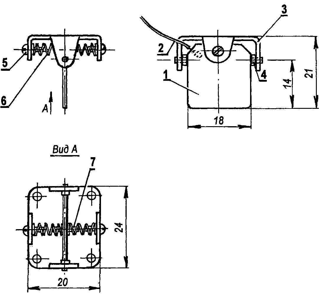
Switch:
1—contact tab (foil controller PCB s2); 2 — connection cable; 3 — the body of the switch (D16 sheet 1,5); 4—spacer (polyethylene); 5 — screw alignment of the return spring; 6—return spring; 7—rod centering return spring
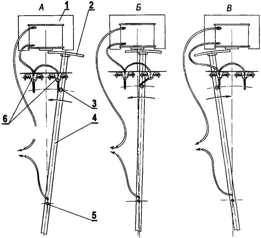
The scheme of commutation of electromagnet:
A—pendulum starts to move, the contactor touches the contact of the petal with the first switch, thereby including a power supply circuit of the electromagnet;—with the approach of the armature to the axis of the solenoid contact tab slides off of the contactor and the power supply circuit of the electromagnet is broken; after a stop in the dead center of the pendulum starts moving in the opposite direction, the contactor in this case of the contact of a lobe of the second switch and includes a power supply circuit of the electromagnet.
The numbers on the diagram marked with:
1—electromagnet; 2—the anchor of the pendulum; 3—barrel; 4—the rod of the pendulum; 5, the axis of swing of the pendulum; 6—the switch
In the upper part of the rod specimen of the fixed anchor will require a strip of soft (annealed) steel with a thickness of 4 mm For fastening it to the rod in the hole drilled in anchor, threaded М12х0,5 mm.
The “engine” of the pendulum is the solenoid — you can do it from the output of the transformer and choke from an old tube receiver, or PA speaker. You only need to touch its core, consisting of the basic W-shaped and rectangular guard plates, the latter should be removed (for solenoid they don’t need), and the first to lay down a new core in the form of the large letter “W”. The coil will need rewinding in accordance with the magnitude of the current, which can ensure the source, for example a charger for a mobile phone. Experience has shown that when using a DC source voltage of 5 V is fine coil of wire of PE with a diameter of 0.3 mm by winding it in bulk to fill the frame. By the way, to the winding with hand drill fixed table vise. The frame will have to fix on threaded rod with two pairs of washers and nuts, and the rod in the Chuck of a drill.
Unfortunately, with just one electromagnet to propel a pendulum will fail — you will need two of the switch closing solenoid only in those moments when the anchor pendulum moving in his direction.
Each switch consists of a contact of a petal made from one-sided glass epoxy. Petal is hinged in the duralumin case and is held in vertical position by a pair of springs.
The process of commutation of the electromagnet shown in the diagram. When the movement of the armature to the electromagnet of the contactor mounted on the rod of the pendulum is pressed to the conductive side of the terminal lobe of the first switch while turning the power to the electromagnet. Last began to attract the anchor, but when you approach the center of the solenoid contact tab slides off the barrel, breaking the supply circuit, and the pendulum continues to move by inertia. Further on the path of the contactor — isolated side contact of a lobe of the second switch, therefore, the contactor free to reject it and continue the movement to stop in the dead center, then swings in the direction of the electromagnet, and halfway to it the barrel will touch the conductive side of the contact of a lobe of the second switch, thereby turning on the electromagnet. Well, then the process will be repeated as long as the device is connected to the current source.
That’s all.
Build a pendulum mechanism is not difficult. The main thing here is to provide the minimum clearance between the armature and the electromagnet (about 0.5 mm) and adjust the position of the contact petals of the switch relative to the contactor. To bring the pendulum in motion, it is enough just to swing.
The watch will be indistinguishable from real vintage pendulum if the glass doors are suspended on chains for two “weights” is to make them the easiest of scraps of dural pipes that need to be polished to a mirror Shine.
In addition, the accuracy of the perception of hours will greatly wliat careful finish of the body.
I. GALKIN
Recommend to read
 SWEEP DRILL
Motorists know how important good contact terminals of the power supply from the battery. Easy to clean inner surface will allow a drill or electric screwdriver: enough is inserted in... …YOU TOUCH THE LEVER — THE PART WILL CLAMP
The simplest collet was developed by the students in the CPC Leninsky district of the city of Alma-ATA. It can be used quickly and reliably to clamp cylindrical parts, shafts, axles,...

 In other houses they are — big old clock in the wardrobe of polished red wood, with pendulum and two big shiny weights on chains. In those hours, something mysterious is through them as if time itself speaks to us about the past and about the present and about the future…