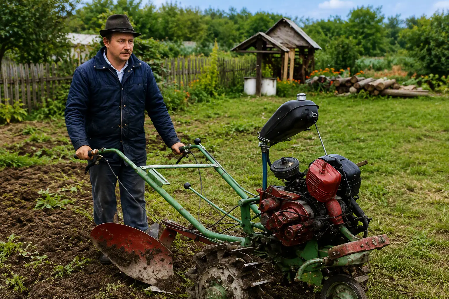
For my first walk-behind tractor, I used the Vyatich as a basis; its technical description and sketches of its main assemblies and parts had been published in Modelist-Konstruktor magazine. However, my capabilities and material and production resources differed from those available to the designer of the Vyatich. The result was a homemade machine that bore little resemblance to the original design.
Although this agricultural machine, assembled from whatever parts were available, did not look flimsy, it was no match for the heavy loams of our Non-Black Earth Region: it slipped and quickly dug itself into the ground. Despite its low weight, neither the fairly powerful engine from an Elektron motor scooter nor the “off-road tires” with spikes welded onto the lugs helped. After struggling with this wretched walk-behind tractor during the sowing season, I had to dismantle it so that by summer I could build myself a sturdier motorized assistant capable of working equally well on different soils and in any weather.
The main requirement I set when designing the walk-behind tractor was the extensive use of worn assemblies from domestically produced machinery with minimal modifications. Besides, I already had some experience, plus accumulated knowledge multiplied by patience and hard work… The result was a reliable farm machine adapted to local conditions (Fig. 1), which I named NLS-2, or simply “Nils”. I am confident that if it ever develops any fault, I will have no particular repair problems. In most cases, everything will come down to replacing the failed assembly or part.
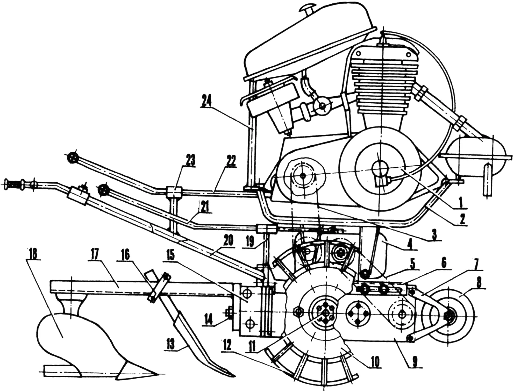
1 — IZH-P-3 power unit; 2 — engine subframe; 3 — high-speed transmission chain; 4 — adapter gearbox (final drive with locked differential); 5 — low-speed transmission chain; 6 — sliding chain tensioning mechanism; 7 — auxiliary wheel bracket; 8 — auxiliary wheel; 9 — main gearbox; 10 — main wheel (from an electric cart, 2 pcs.); 11 — wheel-locking screw; 12 — lug; 13 — cutting blade; 14 — M16 nut of the fastening and adjustment stud; 15 — plow penetration adjustment unit; 16 — cutting blade mounting unit; 17 — plow beam; 18 — plow; 19 — gearshift lever bracket; 20 — walk-behind tractor control handlebar (2 pcs.); 21 — gearshift lever; 22 — reverse lever; 23 — reverse lever bracket; 24 — fuel tank bracket. Parts 1, 2 and 4 are from an S3A motorized invalid carriage; parts 7, 8, 13, 16, 18, 20, 21 and 22 are from decommissioned agricultural machinery.
Take the power unit and engine subframe, for example. Like much else in the NLS-2 design, they are industrially manufactured components taken from an S3A motorized invalid carriage without any modifications. Or consider the adapter gearbox: it is the final drive from the same vehicle (i=2.08), with its differential locked. Locking it is not difficult. You only need to weld the output half-shaft journal to the bushing on which the bearing is seated. This welding can be done without even dismantling the differential; simply protect the ball cage with asbestos or another non-combustible material.
The walk-behind tractor’s successful operation is largely due to its multi-stage transmission layout, which, unlike “standard” counterparts, provides a higher gear ratio and corresponding output torque and tractive effort. In addition to the adapter gearbox, the kinematic layout includes a homemade main gearbox which, together with the final drive and wheel pair taken from a decommissioned domestically produced electric cart, forms a highly efficient propulsion system.
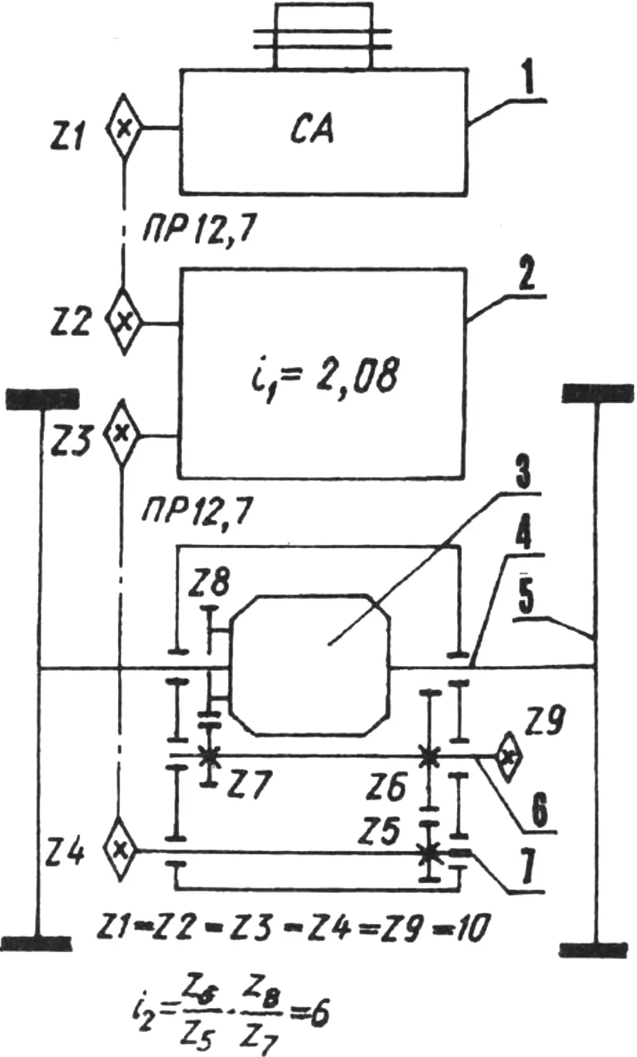
1 — power unit; 2 — adapter gearbox; 3 — main gearbox differential (from an electric cart); 4 — half-shaft (from an electric cart, 2 pcs.); 5 — plowing wheel (from an electric cart, with welded lugs); 6 — intermediate shaft (with power take-off); 7 — drive shaft.
The drive chains are tensioned by a special mechanism fastened with studs to sliders made from steel angle. The sliders can also move, loosening or tensioning the drive chain. For this purpose, slots are cut in the sliders, and M10 fastening bolts and two adjustment screws are provided (not shown in the drawing).
The main gearbox is one of the most labor-intensive assemblies. Its housing is welded (Fig. 4) from pre-cut 10 mm steel plates, with reinforcing discs where the bearings and their screw-mounted covers are installed. The welds are continuous to prevent oil leakage. A U-shaped bracket is welded to the rear wall of the gearbox (relative to the direction of travel) for attaching a cargo trailer—which turns the Nils into an articulated-frame mini tractor—or trailed agricultural implements. A plow, for example, is attached through a special penetration unit that adjusts how deeply the share enters the soil.
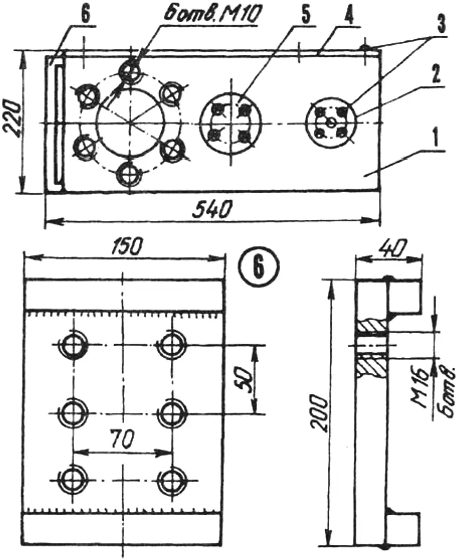
1 — welded housing (steel, s10 sheet); 2 — through-bearing cover (2 pcs.); 3 — M6 screws (46 pcs.); 4 — gearbox cover (steel, s10 sheet); 5 — blind bearing cover (2 pcs.); 6 — welded bracket for trailed implements (steel, s16 plate).
The gearbox cover is also made from a 10 mm thick steel plate. It is attached to the housing with M6 screws and an oil-resistant gasket.
The shafts and cylindrical spur gears were taken from agricultural machines that had reached the end of their service life. If possible, however, it is better to make new ones, bearing in mind that the intermediate shaft also serves as a power take-off. The gearbox’s overall ratio is i = 6, its gear module is m = 2 mm, and the working tooth width is 15 mm.
The differential in the Nils walk-behind tractor’s main gearbox came from a decommissioned domestically produced electric cart made before 1980, when this component was manufactured in a shortened form.
There is little point in giving a more detailed description of the gearbox design, since every home builder has different capabilities. Only the type of lubricant is worth mentioning. Nigrol or Autol oil is best suited to the Nils. The gearbox should be filled to one-third of its height.
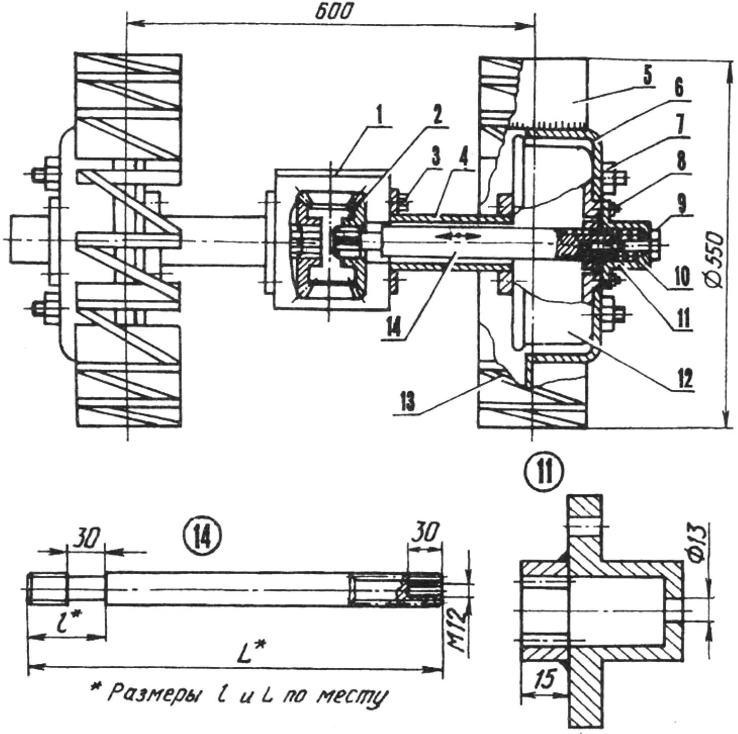
1 — main gearbox housing; 2 — differential; 3 — M10 bolt (12 pcs.); 4 — half-shaft housing (2 pcs.); 5 — straight lug (steel, 200×100 plate, s16, 32 pcs.); 6 — wheel disc (2 pcs.); 7 — M16 nut (12 pcs.); 8 — shaped M10 nut (12 pcs.); 9 — M12 wheel-locking screw; 10 — cylindrical spring (2 pcs.); 11 — cup-shaped hub (2 pcs.); 12 — casing (2 pcs.); 13 — angled lug (250×20 steel plate, s10, 32 pcs.); 14 — sliding half-shaft.
Parts 2, 3, 4, 6, 7, 8, 11, 12 and 14 are from an electric cart.
Wheel locking is a rather interesting design solution and, more importantly, an essential feature for a walk-behind tractor. On the Nils, it works as follows. A cylindrical journal is machined into the splined end of the right half-shaft slightly beyond the depth of the spline groove, while a threaded hole is made in the opposite end. When the M12 adjustment screw is turned, the half-shaft shifts into the differential under the force of the cylindrical compression spring, disengages from the splined bore of its original gear and engages the adjacent one, thereby locking the wheels.
The NLS-2’s working (plowing) wheels are based on the standard wheels from the same decommissioned electric cart. The manufacturing process is quite simple. Sixteen slots are cut into the rim of each disc, and steel plates serving as the bases for the lugs are welded into them. Crosspieces welded between the plates form the zigzag rims of the plowing wheels.
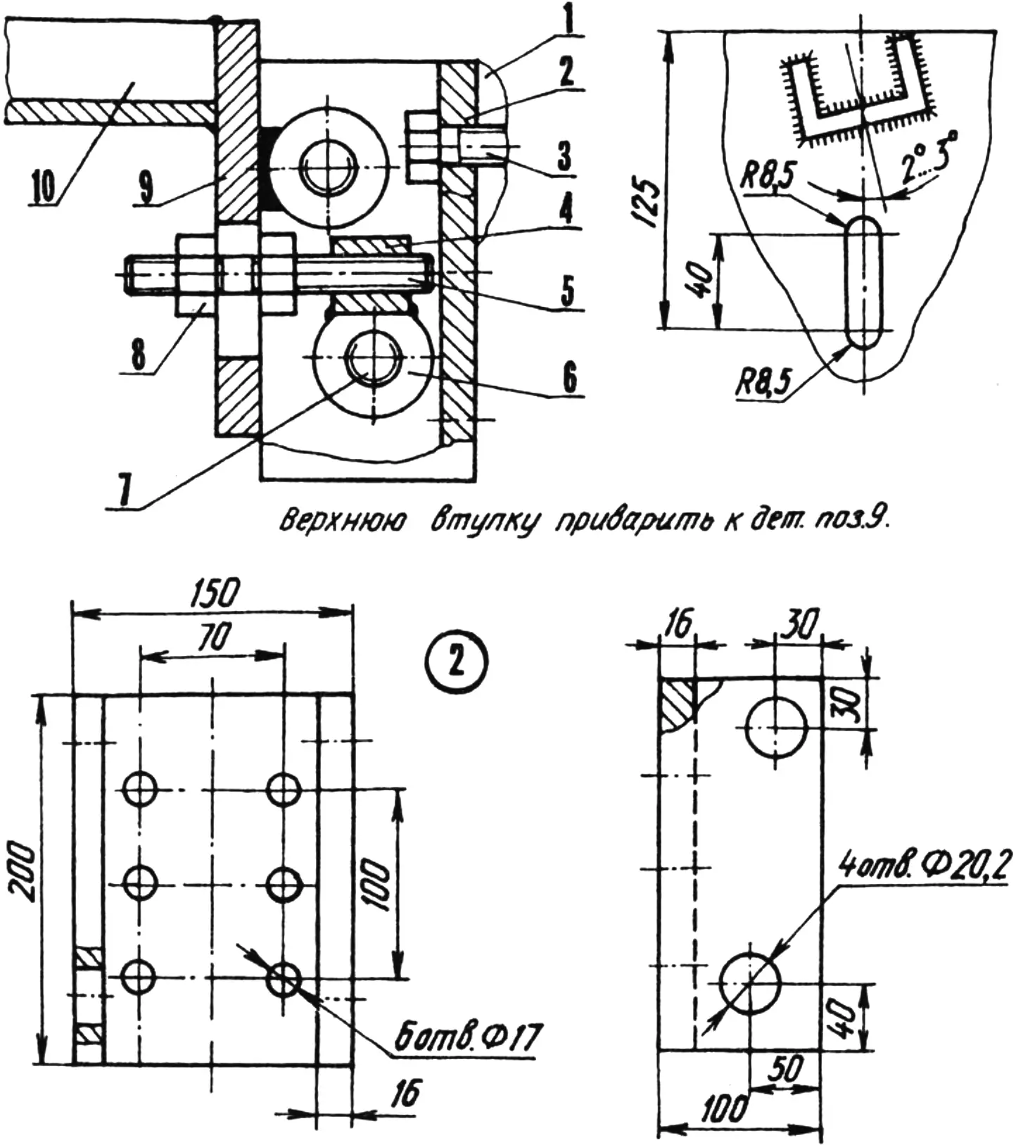
1 — trailed implement mounting bracket; 2 — welded unit housing (steel, s16 sheet); 3 — M16 screw (6 pcs.); 4 — M16 adjustment nut; 5 — M16 stud (L130); 6 — bushing (2 pcs.); 7 — axle (M10 bolt, 2 pcs.); 8 — M16 nut (2 pcs.); 9 — plow beam heel (steel, 200×118 plate, s16); 10 — plow beam (No. 5 channel, L800).
The plow penetration adjustment unit is likewise simple and, as practice shows, highly effective (Fig. 6). It consists of a welded U-shaped housing whose locating and limiting projections hold the heel of the plow beam, allowing it to pivot vertically on a sleeve-and-axle joint. The required angle is set by an M16 stud, which is then secured with a nut. Because the channel of the plow beam is welded to the pivoting heel with a slight turn toward the side to which the plow throws the soil, the plow remains correctly aligned during operation.
The cutting blade is also attached to the plow beam. Its required angle to the soil and depth are set using a standard clamp with a backing plate and two M12 bolts with nuts. At the front of the Nils, an auxiliary wheel is mounted on a V-shaped bracket. Its purpose is to make transporting or reversing the walk-behind tractor easier.
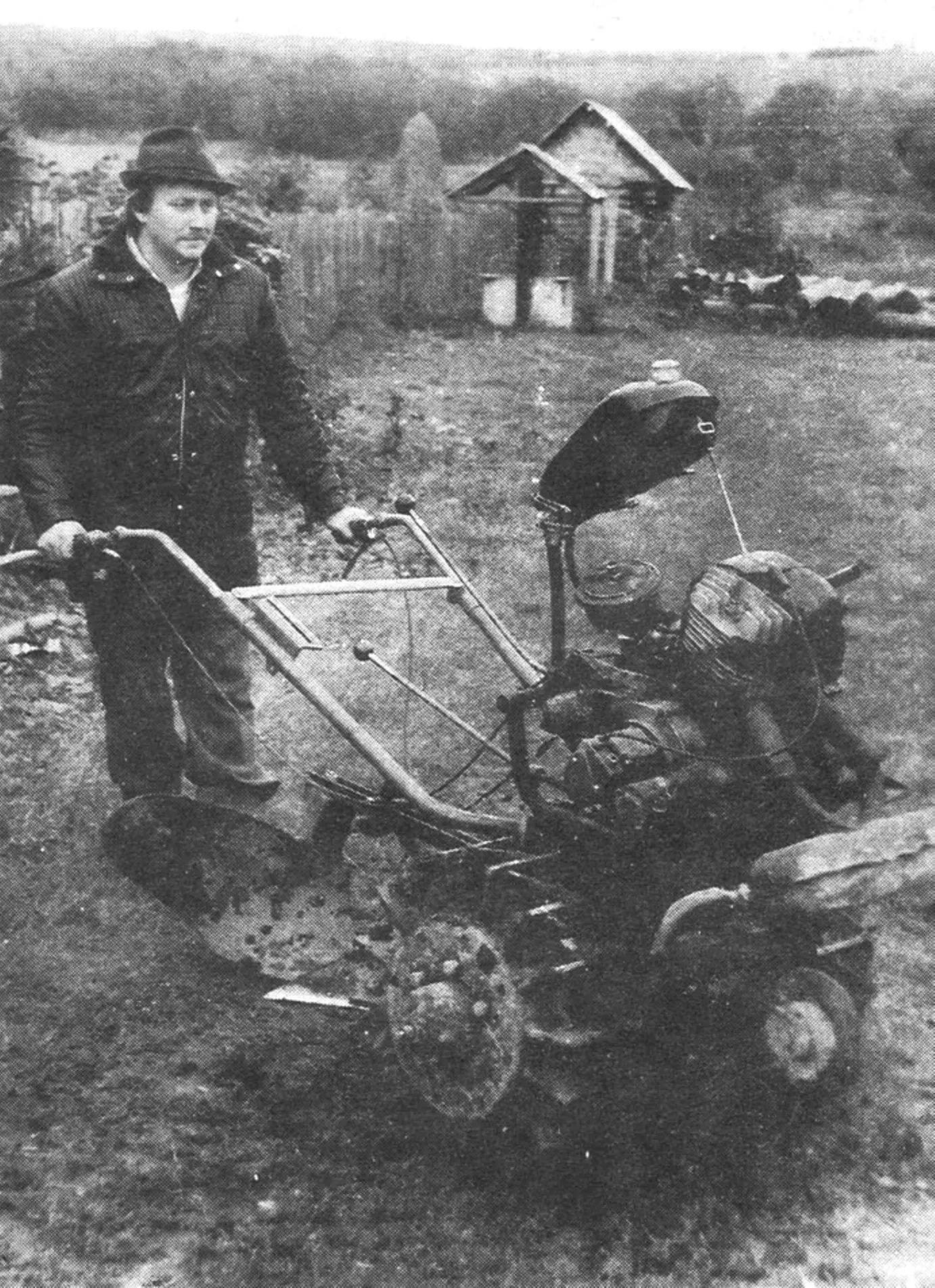
The NLS-2 is controlled by two handlebars from a motor mower, mounted with a slight offset to the left in the direction of travel to help keep the machine in the furrow, as well as auxiliary gearshift and reverse levers.
I plow the main part of the plot with the Nils in second gear, and particularly heavy soils in first. Guaranteed productivity is up to three to five sotkas (300–500 square meters) per hour.
Modelist-Konstruktor No. 2’99, S. KISLYAKOV
Recommend to read
 “HAZIRS” TOOL
Every good master has his way of placing the tool. I think readers may be interested here is a version of the wall storage of the metal strip, for example, edging, containers. By bending... “ROTOR” WINNERS
Model rotocut. In the championship of Russia for sport flying the first prize winners in the class of models of steel rotochutes Larisa Ivanova and Alexey dirt. Today, our material about...
