ALL FOUR LEADING

ALL FOUR LEADING
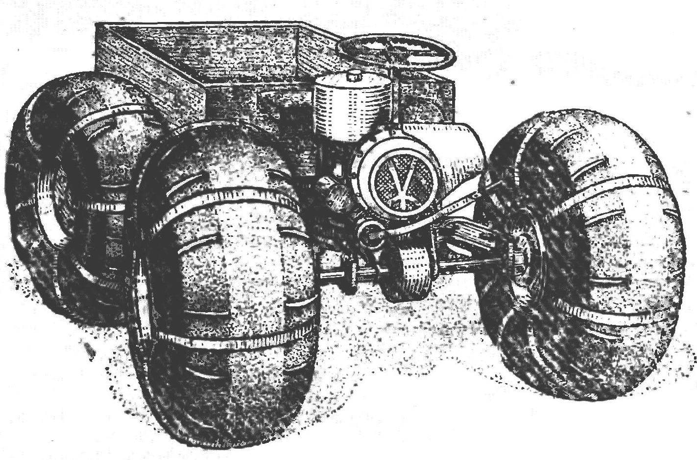
The vehicle is made according to the scheme proven by the tractor “Kirovets”. He has the same “breaking” the frame and drive on both bridges. What gives? First, the permeability. Frame, continuously curving, as if tracking the terrain. All four wheels are constantly in contact with the surface. This eliminates the overload of individual wheels and slip them on uneven ground and secondly, the maneuverability. The hinged frame is sensitive to even the slight deflection of the steering wheel and allows you to turn almost on the spot. Thirdly, constructive simplicity. In this scheme, you can use exactly the same front and rear axles. Simple turns and the engine mount.
The frame consists of two main parts, connected in the middle by a hinge with a vertical axis of rotation. The front part is welded rigid node on which you installed the axle, engine, fuel tank, foot controls and the driver’s seat. Left carrying the arc of the frame also serves as a silencer.
 
Hinge with a vertical axis of rotation consists of two forks, United powerful fingers. The fingers of bolts attached to lugs of the rear fork, and the front turns in a thrust and needle bearings.
 
Chassis (on the top view the engine and seat conventionally not shown)
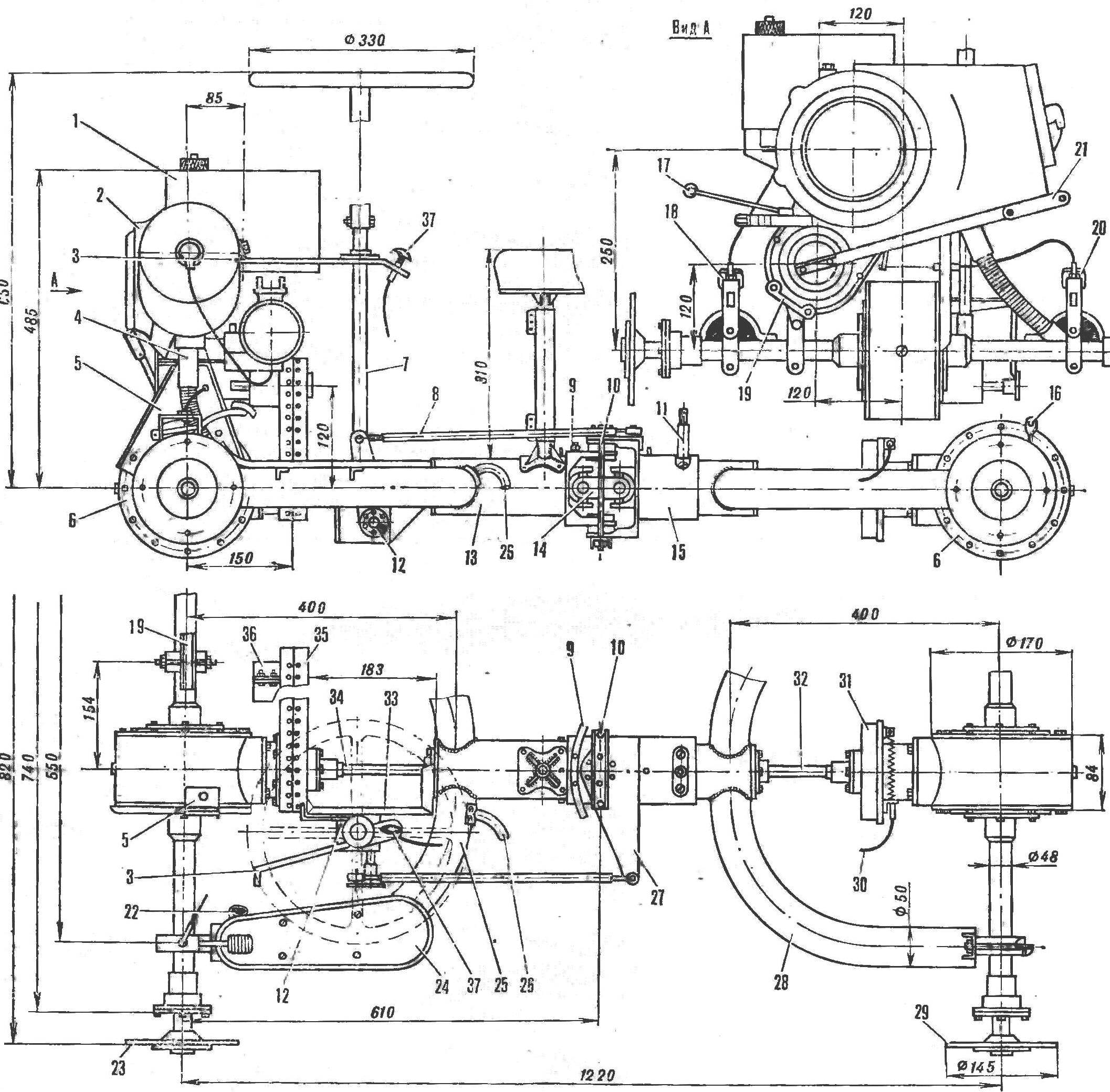
Suspension (from the top view the engine and seat conventionally not shown):
1 — fuel tank 2 — motor, 3 — bracket fastening the steering column, 4 — exhaust pipe 5 — the Central mount of the engine, the housings of the differentials, 7 — steering column — steering rod. 9, 10 — limiters of the angle of “break” frame, 11 — limiter-bolt body 12 — steering worm gear, 13 — cover front propeller shaft 14 — the connecting link. 15 — cover the rear of the driveshaft, 18 loop body mounting, 17 — shift lever. 18 — accelerator pedal 19 — lower bracket engine mounts, 20 — clutch 21 — day, 22 — the suction inlet of the muffler 23. 29 — flanges axles. 24 — tripping. 25 — supporting the arc of the frame (muffler). 26 — exhaust pipe. 27 — bellcrank steering. 28 — supporting the arc of the frame. 30 — lock brakes 31, the brake drum 32 — rear drive shaft. 33 — bracket steering gear 34 of the front driveshaft. 35 — chain box, 36 — the rear bracket of the engine mounts. 37 — brake handle.

 
So the wheels are not rubbing against each other when you “break” the frame around a vertical axis, the hinge has limiters that are installed respectively at the front and rear forks: slightly curved and tapered for stiffness-hook and two studs on the ends of the channel brackets. The rear part of the frame to the attached axle, brake and detachable body is movable, the hinge of her — with a horizontal axis of rotation. But it works a little differently: to the rear fork riveted fixed cover with internal thread, to which is screwed a bronze nut. She serves as a bearing for a movable cover of the rear part of the frame.
 
In the sleeve, this casing is held by a stud, screwed into the reinforcing lining. She’s the limiting angle of “break” the frame relative to the longitudinal axis of the vehicle. The value of the angle depends on the length of the groove is sawn in a stationary casing and the sleeve.
 
The engine of the VP-150M installed across the movement to take less space, and the fan air cooling had the most favorable conditions for work.
 
Joint sprocket drive with differential and front driveshaft
The articulation of the drive sprocket with the differential and front driveshaft:
1 — pinion bevel gears 2 and the differential case, 3, 7 — tapered roller bearings, 4 spacer, 5 — shim, 6, 12 — pins MB, 8 — cuff, 9 — housing bearing Assembly, 10 — bolt M4, 11, 18 — halves of the casing 13, the inner flange, 14 — rivet 0 3 mm, 15 — sprocket driven, 16, 20 — wiity M4, the 17 — panel, 19 — loop bracket steering gear, 21 — nut M 14X1,5, 22 — outer flange, 23 front propeller shaft.

 
Mounting brackets are located as follows: the Central and most powerful — on the housing of the differential, under the cylinder of the engine, the lower right beam of the bridge, under the Carter and the rear on the casing of the chain transmission.
 
To the crankcase of the engine mounted metal fuel tank capacity of 5.5 liters; the fuel in the carburetor flows by gravity.
 
Controls are placed on beams of the front axle: left pedal clutch, right side gas. For the convenience of the driver near the pedals installed foot pegs.
 
Installing the brake drum
Install the brake drum:
1 — front driveshaft 2 — outer flange, 3, 8. 12 — M6 studs, 4 — brake drum 5 — inner flange, 6 nut M14, 7 — brake disc 9 — the case of the bearing unit, 10 cuff, 11, 15 — tapered roller bearings. 13 — shim, 14 — spacer, 16 in the differential case,17 — pinion bevel gear.

 
Gears are shifted by hand using a lever with a ball on the end welded to the toothed sector.
 
The engine starts with the kick starter with the handle instead of folding pedals.
 
The exhaust gases from the cylinder for corrugated pipe fall into the left support tube of the frame as the muffler and out the exhaust pipe under the seat.
 
Transmission the vehicle is symmetric about the vertical axis of the “break” the frame. Torque from the engine circuit is transmitted to the propeller shafts, and from them through bevel gears and differentials — axle shafts bridges. Drive shafts machined from bar. In the middle of them — under the seal of the neck and at the ends of the slots. Driveshafts with universal joints (including connecting link) is taken from the motorcycle “Ural”. They rotate in bronze bearings which are lubricated from time to time through a thin tube ttings bred out.
 
The external splines of the propeller shafts included in the outer flanges connecting them with the shafts leading bevel gears gears. The rear shaft is equipped with a brake of the scooter “Vyatka”: brake disc with pins attached to the housing bearing
node, and the drum — flanges. The control cable from the disc placed on the steering column.
 
The differentials of the axles on the Rover — traditional design: with two gears-satellites (from the car “Moskvich-412”). The side gears made, and bevel gear taken from the motorcycle “Ural”.
 
Biscuit in contrast to the “moskovichevskoe” is not a spherical surface facing the differential housing, a cylindrical, for simplicity.
 
Bridges are attached to the frame with bolts, bushings and shims. Only on the rear axle bolts still hold the hinges to the body, and the front — mounting brackets of the gas pedal and clutch.
 
Steering consists of a removable steering wheel, vertical column, steering worm gear, two rocking chairs and adjustable pull. The gear ratio of the actuator 1 : 4, which allows to “break” the frame not only in the movement. but in the Parking lot. The force from his thrust is transmitted to the rocking chair, a fork attached to the rear of the frame, and causes it to deviate in one direction or another.
 
The wheel is also structurally simple and identical. Bearing element each of them is aluminum step-
TSA, the ends of which are screwed to the discs of the same material.
 
Design of joints
Design of joints “break” the frame:
1 — cap, 2 — screw M3 {4 pieces), s — body mangetic 4 cuff 5 front prop shaft 6 — front cover 7 — cover, 8 — front seat. 9 height adjustment, 10 — front fork, 11 — tube stop angle of “break” frame, 12 — case needle bearing 13 is sleeve. 14 — stud-stop angle of “break” frame, 15 — brackets pins-limiters, 16 — finger-axle “break” frame, 17 — direction. 18 — needle bearing, 19 — bellcrank steering, 20 — rear fork, 21 — oiler, 22 — limiter-bolt body 23 is a reinforcing lining, 24 movable cover, 25, 27, 33 — bronze sleeve-bearings, 26 — stationary housing 28 — screw M5 (2 PCs), 29 — MB bolt of fastening of a finger-axes (6 PCs), 30 — MB bolt (8 PCs),31 — connector,32 — MB bolt (4 PCs), 34 — cardan.

 
Scheme of transmission
 
Scheme of transmission:
 
1, 3 — axle front axle 2, 10 — differentials, 4 — output shaft motor, 5 — chain gear, 6 – front propeller shaft, 7 — connector, 8— rear drive shaft, 9, 11 — rear axle shaft.
 
Rear axle
 
Rear axle:
 
1 — flange wheels, 2 — gland, 3 — cover, 4 — bearing, 5 — shaft bearing. 6 cuff 7 — retaining ring 8 — axle and 9 — axle shaft. 10, 17 — flanges of the differential housing, 11 — cap, 12 — bevel gear, 13 — pin M8 coupling, 14 — dry 15 — finger satellites, 16 satellites. 18 — stud MB. 19 — differential bearing. 20 — hull shaft bearing, 21 — gasket 22 — halves of the differential housing, 23 — supporting an arc frame, 24 — plug 25 — shim. 26 — ear. 27 — pinch bolt M8, 28 — loop fastener of the body.

 
Wheel
 
Wheel:
 
1 – M8 bolt attachment to the axle flange, 2 — hook (wire Ø 3 mm). 3 — canvas belt, 4 — clip (wire Ø 4 mm), 5 — hole for the valve. 6 — hub 7 — disks. 8 — cover.

 
The body
 
Body:
 
1 — front bracket, 2 side brackets, 3 — rivets Ø 3 mm 4 — M4 screws.

 
Drives wire hooks and brackets attached eight canvas straps hold the bus — two cameras size 720 X 310 mm, nested one inside the other and secure the canvas band with pockets-cleats.
 
The outer end of the hub is closed, protecting its cavity from contamination, and the interior is fitted with four bolts for attaching the wheel to the axle flange.
 
The body is assembled from welded steel frame and a glass fibre laminate panels. The necessary rigidity of the floor give
three channel with brackets for installation on the frame of the vehicle.
 
The weight of the body is only 6.5 kgs, however its dimensions are such that allow an adult to sit without experiencing much inconvenience.
 
Technical care of the vehicle almost minimal. It is sufficient to monitor the level of fuel in the tank, the gear oil in axles and the air pressure in the tires. Yes, occasionally lubricating bronze bushings-bearings through the grease fittings.
 
A. GROMOV, A. TIMCHENKO

Recommend to read

  • SIMPLE, EASY, FISHNETSIMPLE, EASY, FISHNET
    The trailer is made in the club "Tourism, and pedal cars", which I ran for several years. Used in construction sites and technical solutions repeatedly tried and tested in our...
  • “MAGIC” LANTERN“MAGIC” LANTERN
    Good help the Modeler will have an overhead projector, which is easy to make yourself. It can be used to increase or decrease to the appropriate size drawings, projecting them on the...