AND LIFT, AND PLUNGE

AND LIFT, AND PLUNGE

Concerns on rural households do not count. There are those that are associated with lifting, loading or moving heavy objects. But when workers, the performance of such work is sometimes an unsolvable problem.
However, if the farm has a tractor that is not uncommon today, the heavy lifting you can “turn” him, using the hydraulic suspension system. You only need to make a simple device that will allow you to lift loads weighing up to 600-700 kg to a height of three meters.

However, if the farm has a tractor that is not uncommon today, the heavy lifting you can “turn” him, using the hydraulic suspension system. You only need to make a simple device that will allow you to lift loads weighing up to 600-700 kg to a height of three meters.
 
The idea, incidentally, is not new. There is probably not a tractor, which at least once had to use the tractor as a lift. To do this, take the log of average thickness and three-four-meter length, insert it at one end between the shaft longitudinal (bottom) pull the hitch and rear axle housing and at the other end to tighten the loop of rope. That’s all, the simplest lift is ready.
 
The device is quite efficient, but not safe. The plank under load, at the crucial moment can break or slip on hanging to the side. So it is better to make the metal version.
The design is very simple and consists of only three homemade and one of the factory sites. This is the main boom, an additional pull-down arrow “pick-up-triangle” factory manufacturing and the tip of the “triangle” which hinge but attached to the main boom.
 
Let us examine first, how does the lift, and then back to the device and the sizes of each makeshift site.
 
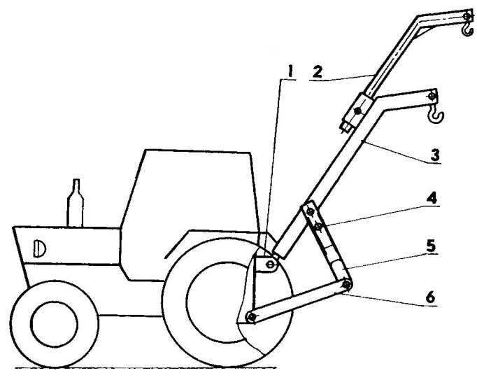
The scheme of placement of the lift on the tractor MTZ-80
Layout of lift on the tractor MTZ-80:
 
1 — bracket Central thrust of the tractor hitch; 2 — extendible boom; 3 main boom; 4 — tip “triangle”; 5 — “pick-up-triangle”; 6 — longitudinal traction hitch

 
Tip
The tip of the “triangle”:
 
1 — the eye (2); 2 — stiffener plate (4 PCs); 3 — trim with opening latch “triangle”; 4— joint (channel No. 8, L143, 2); 5 — jumper; material det. 1,2,3,5 — steel sheet with a thickness of 5 mm

 
Boom lift
Boom lift:
 
1 — ball bearing; 2 — main boom; 3 — extendable boom; 4,5 — hooks; 6 — bolt ball bearing; 7 — pad; 8 — lock retractable boom; 9 — guide rail retractable arm; 10,11 — axis hooks
 

Those who deal with tractors, don’t need to explain what “pick-up”. It is mounted on the mounting node triangular in shape (it was called the “triangle”), designed for mounting (connection) of the tractor with some mounted or semi-mounted agricultural implements and machines. They all have reciprocal connections with the “triangle” and groove, repeating its shape. Because “triangle” and called a “coupler” that allows it to attach machinery to the tractor without assistance and in a matter of minutes. Drove in reverse to the desired weapon, failed hydraulics “triangle” under the fastening groove, raised suspension and — click! The car is already on the sample. Quickly and safely. By the way, I’m going to remake a “pick-up” all their agricultural aggregates. So it is very convenient.
 
The self-made lifting device works as follows. When you move the lever of the directional valve in the position of a FLOATING charge under the action of gravity of the boom lift is lowered until it stops. The main boom is in the horizontal position, its curved end touches the ground. This also applies to the case when the extended and additional boom, the end of which is bent at the same angle.
The load is attached to one or both arrows at once, depending on its shape and mass as well as height. The heavier the load, the smaller should be the shoulder of application of force and lifting height, otherwise the hydraulics simply can not overcome the force of gravity.
 
When the cargo is fixed, it can be raised. For this purpose, the lever of the directional valve slowly translate to the position of the LIFT. Linkage rod begin to move up and through the triangle and its tip is exposed to the boom. The cargo off the ground. You can now carefully maneuver.
 
Being in the right place, we begin to lower. For this purpose, the lever of the directional control valve very slowly move from position fix to position FLOATING. Upon reaching the desired lowering speed, hold the lever until the full load lowering.
 
And now a closer look at the device of each of the self-made lift components. For the manufacture of the tip it took a channel 8 and a steel sheet thickness of 5 mm. Of the same materials made by ten parts: two bearings, two jumpers, two eyes and four scarves. The slot in the back of the jumper is a groove for a retainer, which is equipped with “triangle”.
 
All the parts are connected by welding with double fusion seams. The lugs are drilled through holes with a diameter of 26 mm under the finger mounting end of main boom. Securing the arrow through the upper hole in the tip, you can increase the lifting height, and using the bottom hole is to get to lower lower the boom (this is necessary when some work).
 
Itself the main boom is made of steel area 90x56x6 mm, to which is welded the entire length of the lateral shelf of the strip thickness 8 mm. Turned steel channel with dimensions 90×64 mm. in addition, under the Central hole is reinforced channel plate sizes 300×64 mm of the same steel strip with a thickness of 8 mm.
 
One end of the boom is bent at an angle of 40 degrees and is equipped with a mounting hook from the slings of the crane. To the other end with two bolts M 14×1,75 attached to the ball support from the Central thrust, which boom is this thrust is installed in its socket.
 
On top of the main boom is welded a section of pipe with a diameter of 76 mm. This tube is a guide for a floating boom which allows you to extend the length of the shoulder lift almost a meter.
 
Additional boom made of thick-walled pipes with a diameter of 60 mm. along the entire length of pipe drilled five holes in order to fix it in the guide with different length extensions. A retainer is a steel finger with a diameter of 14 mm. the end of the extendable boom is also equipped with a mounting hook, but smaller.
That’s all the device. If you have the necessary materials and tools, chief among them — welding machine, the lift can be made in one day. I say this based on our own experience.
 
Use, despite the simplicity of the design, from the lift a lot. Some only work with it, not had to perform! And oak pillars to the garage to put, and logs to stropit, and a variety of boxes, containers, and even the machines in the vehicle shipping, and on-site work — feeding on the walls of bricks, cinder blocks, beams.
 
And all this took a matter of minutes, turning from the problem to the interesting case in which get pleasure from the process. And a positive result is guaranteed, as wherever the person is for their needs that fits mechanical AIDS. Especially made with your own hands!
G. LEGOSTAEV, farmer, S. Mishkino, Bashkortostan

Recommend to read

  • CHEST-SAMOBRANKACHEST-SAMOBRANKA
    The need to eat regularly is a normal human need. And if at home and at work, and even more so at the organized holiday food established, travel (whether by foot, Bicycle or car) with...
  • THE CAR IS A DREAMTHE CAR IS A DREAM
    If "Attesi-TX" able to enchant you just the same as at the time, and me, I think I may be able to help you make this very simple, compact and as a result, cheap and affordable car....