
 In the house of the manor type of water demand is far higher than in a city apartment. Because usually when there are a garden, vegetable garden, and every fowl in the yard, which water is also required. The process of delivery in large quantity in the buckets is not only long, but tedious, even if the source (be it well or river) is not far.
Therefore, before the hosts sooner or later the question of the mechanization of food supply. Someone builds a pipeline, ditch, and someone comes up and embodies the combination of different water supply systems.
I chose the pipeline option: it is the most economical of all the above and provides year-round operation of the system in our climate with frosty winters.
My water system is designed to ensure that watering plants in the garden in the summer and year-round household water needs. Looking ahead, I will say that for the system used steel water pipe with orifice 3/4 inch and the corresponding (they put) rubber (but can be plastic) connecting hoses.
The water source is a conventional well of the most common reinforced concrete rings with a diameter of 1 m and height 0.8 m. Distance from ground surface to the water surface is about seven meters. I must say that I have had a single-phase electric pumps “Agidel” the depth of pumping of water was the ultimate. I had to think about how, without changing the equipment (the same pump), to make possible the diversion of water from greater depths.
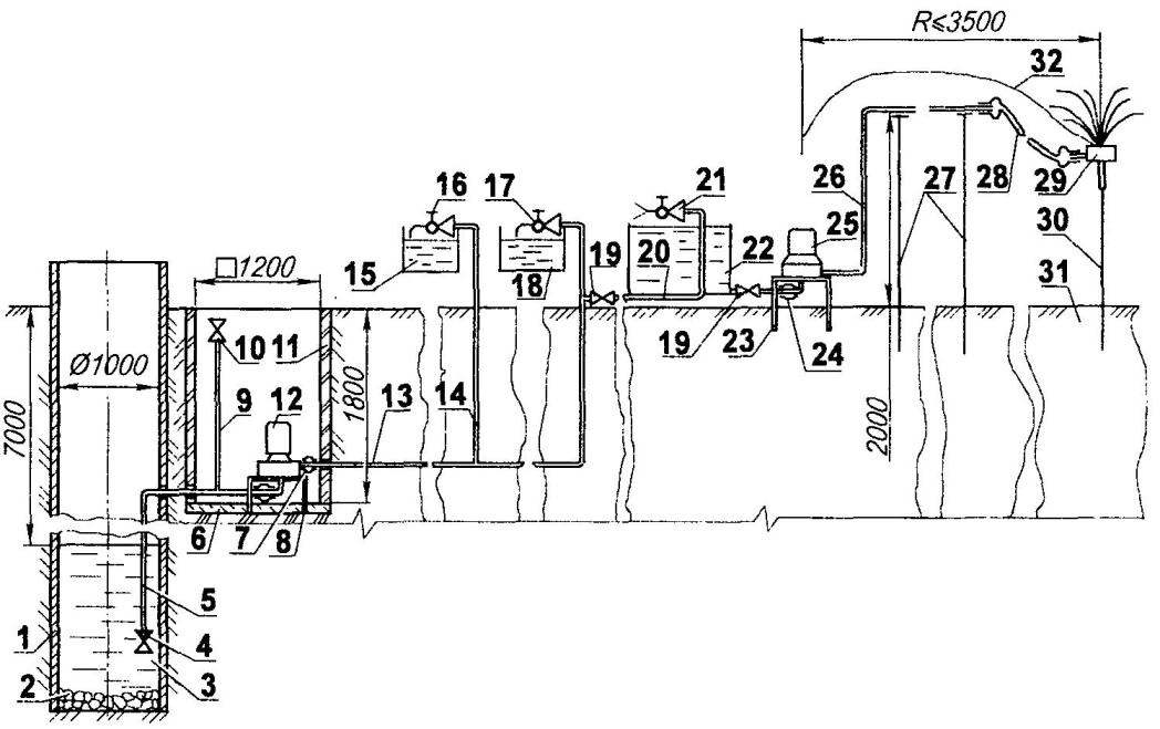
The house water supply homesteads for domestic use and watering garden plants (all pipes — water, with orifice 3/4″, outer diameter 26 mm):
1 – a wall structure (reinforced concrete ring); 2 — stone bottom of the sketch; 3 — water; 4 —valve; 5—a reception pipe; 6 — the bottom of the pit (concrete); 7 elastic coupling (rubber hose, 2 PCs); 8 — area under the pump “Agidel” (steel, corner 45×45): 9 filler neck; 10 — valve filler neck; 11—wall of the pit (ceramic bricks); 12 – electric “Agidel”; 13—diverter rough; the 14-bath branch; 15 – bath tank; 16—bath faucet; 17 – kitchen faucet; 18—cooking tank; 19 – valve of a watering taps and tank; 20—a pipe of a watering tank; 21—watering valve; 22– watering tank (capacity 3.5 m3); 23—area watering pump (steel, 45×45 area); 24—the elastic coupling (hose, 2 PCs.):, 25— a centrifugal electric pump (3-phase, N=1.5 kW, n = 3000 Rev/min) 26—irrigation pipe; 27 — supporting stand of a watering pipe (reinforcing bar Ø12, as required): 28 — irrigation sleeve (rubber hose); 29 — irrigation spray head; 30 — support strut sprinkler heads (reinforcing bar Ø12); 31 —pound (soil); 32— spraying stream of water
The decision came as if by itself, but rather along with the answer to another question: how to ensure the functioning of the water system at subzero temperatures? Actually, the last question someone decided for me a long time—to bury the pipe deeper in the ground (below the maximum depth of soil freezing). But along with the pipes to drop below the pump.
This near the well dug pit almost two-meter depth size in terms of 1200×1200 mm. the Bottom of the pit was filled with 100 mm layer of concrete and wall thickness of a half-brick laid ceramic (red) bricks in cement mortar. While the concrete mixture is still not grabbed, slammed to the floor legs pre-welded reference sites. After curing of the concrete has mounted on it a centrifugal pump “Agidel”. The input and output pipes connected rubber hoses with clamps — with receiving and discharge pipes, respectively. At the free end of the receiving pipe lowered into the well below the depth of the average water level, is mounted a check valve.
About this small but important device (check valve), I think, worth discussing in more detail because of its smooth operation depends on the next launch system after each off (figuratively speaking — “without nerves”, and specifically, without filling the working chamber of the pump and pipe the water through welded to discharge pipe outlet with a valve).
Before I came to the described design of the check valve, manufactured and tested a few different known variants: the ones that have worked better, but 100% retention of water in the system for a long time (at least a day) not given to any one.
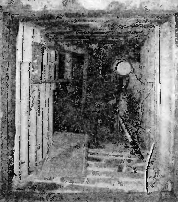
The location of the pumping station in the pit
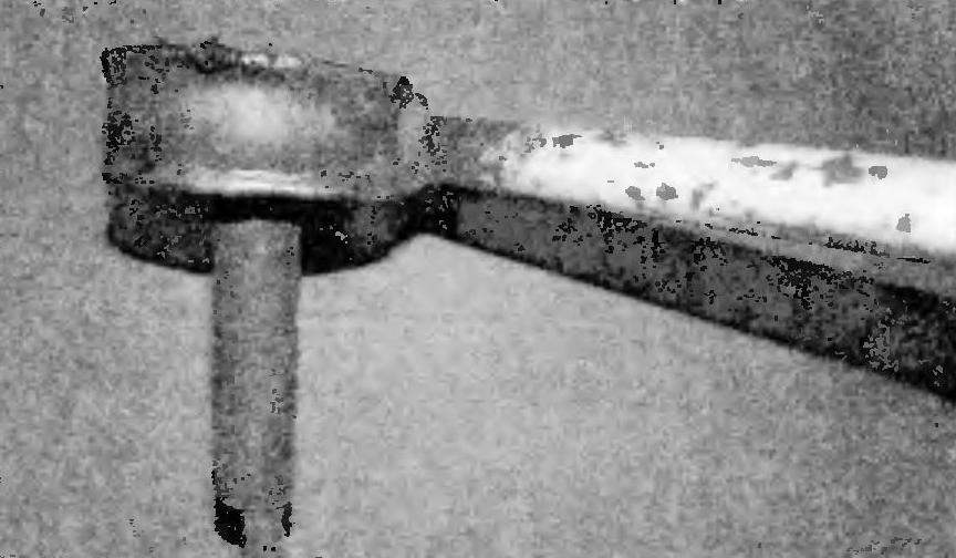
Irrigation head Tina “tin cans” of his own design
In the end, retreated from the canons and made the valve design. It is very simple and consists of a circle cut from a sheet of elastic (“vacuum”) of the rubber thickness of about 4 mm. In circle made a slit in the form of a semicircle but a smaller diameter, which selects the “petal” (or can be called “tongue”). The valve is placed in the body carved out of stainless steel (but can be made from plastic, nylon, Teflon, etc.). Top housing screwed the adapter which presses the valve flange, and the bottom he is covered by a mesh grille that is approximately the same as the grinder. Here I note that the slot in the valve can be a little more of a semicircle, or less than, depending on the pump power. With more power — you can make the slot smaller, and Vice versa. The length of the slot also depends on the thickness of the rubber sheet and its stability.
A bypass pipe laid under the ground (at the same depth at which pump is installed) and summed up under the house to the kitchen to fill the reservoir from which water is to be consumed as needed for domestic purposes. The tank is made of stainless steel. At first I wanted to install on the tank a water level indicator. But when her arrival on the wall of the tank outside condensation, which clearly shows the filling level of the tank water.
From the outlet pipe under the ground made by another branch in bath. At the exit of the bath the pipe the valve is installed.
To the discharge pipe (under the house) welded onto the outside of the pipe with the valve. The valve, with the help of sleeves and connectors, attached a pipe to 3/4 inch tap on the end through which water is supplied in a 3.5 cubic capacity, which is then used for watering garden plants.
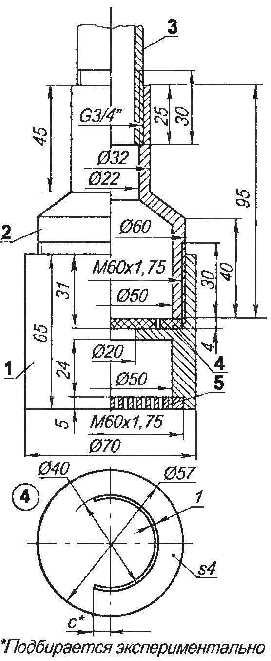
Check valve:
1 —case (steel 45, the range 70); 2—Cup (steel 45, range 60); 3—receiving pipe 4—valve (vacuum rubber, s4); 5—mesh-grille (steel 45, range 60)
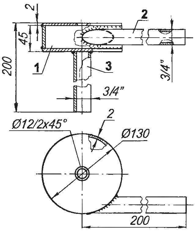
Irrigation head:
1—housing (stainless steel, sheet s2); 2—receiving pipe (pipe 3/4″); 3—shell pipe (pipe 3/4″)
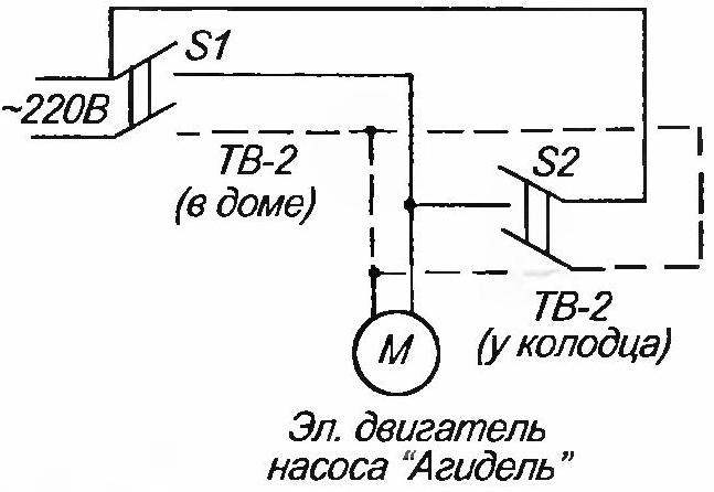
Electrical connection diagram pump “Agidel” (the dashed line shows the wiring connection at the well)
In the tank the water is usually heated during the day to ambient air temperature (and in Sunny weather and above). In the evening, during watering, water from the tank with a pump providing pressure to two atmospheres, through pipe, raised above the ground on pillars two meters and discharge hose is served to the place of the garden, where trees, shrubs and other plants. This three-phase pump, centrifugal type, capacity of 1.5 kW at 3000 rpm. Brand calling it as it is assembled from several suitable. Small plants prefer not to irrigate, and irrigate. It also used different irrigation first head of industrial manufacturing. But so very often they are clogged because the water is not filtered. In the end, they were replaced with homemade.
New head compared to the industry quite simple, but virtually trouble free. It consists of a cylindrical body, resembling a tin can, welded to it (tangentially) of the inlet pipe. Another pipe (axial) welded to the bottom of the cylinder, the deaf, it only serves to ensure that the crown could impose on stuck in the ground metal or wooden rod. In the lid of the cylinder on the axial center of the drilled countersunk at 45° hole 12 mm in diameter through it, the water is sprayed around by the fan in a radius of 3-3. 5 m.
The casing head is welded from 2 mm sheet stainless steel and pipes — water pipe 3/4 inch. When one area around the head has enough water, carry the irrigation head with the hose on a nearby terminal.
Electrical wiring diagram of the pump such that it can be inserted from both at home and on-site, at the well.
In the winter garden part of the system off—block valve on the discharge pipe. The pit closed with a sheet of slate and fall asleep first with sawdust, and on top of snow, and the system does not freeze even in severe frosts.
V. KURAKIN, Saransk
Recommend to read
 A FIGHTER WITHOUT A KEEL…
Seaplane Hansa-Brandenburg W-12. The date of establishment of the naval aviation of Germany is considered to be 26 Oct 1910. On that day Admiral Alfred von Tirpitz signed a Directive on... BELTS GLOVES FROM
An open belt is rubber ring at the tape recorder or a player — it happens not so often, but because surprised. However, a good housewife can always find an old rubber glove. Select the...
