 House mansion type, in which there is subsistence farming, with several supporting buildings for their maintenance and repair woodcutting machine called among artisans circular saw is a must.
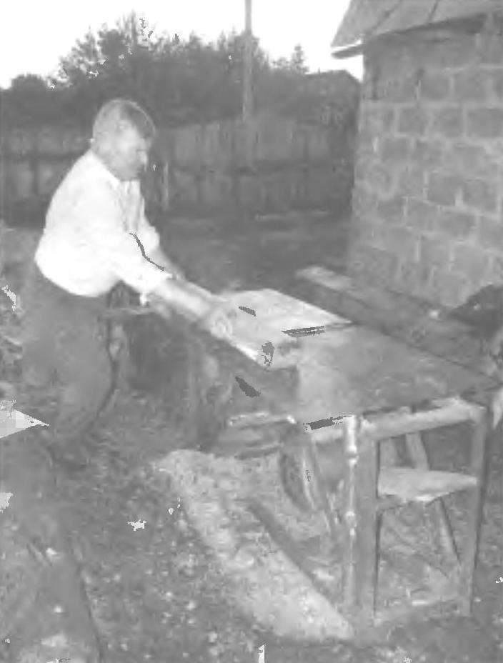
There is such a machine and I have also homemade, like most of my “backyard” technology. I did it with the expectation that it could and carpentry-joinery to carry, wood to saw, and if necessary — and metal cut out, replacing steel saw cutting disc sand around.
The layout of the machine, so to say, classic. Drive, working bodies are mounted on a common simple frame.
The machine is driven by electric. Motor power 4,5 kW number of revolutions 3000 per minute is powered by three-phase AC voltage of 380 volts. On the frame it is mounted so that the tension of the driving V-belts is carried out by the force of his gravity.
Ordinary frame, welded. Stand made of steel angle corner 45×45 mm, struts — from the corner of 35×35 mm, and piping for both the lower and upper rectangular tube 60×30 mm. From this same tube is made for two binders of the upper cross member. To a pair of front struts are attached with four bolts M10 slider (two steel strips 455x50x10 mm) of the motor. The struts serve and guide when the tension of the drive belts: in the struts together, the mounting holes are made longitudinal grooves.
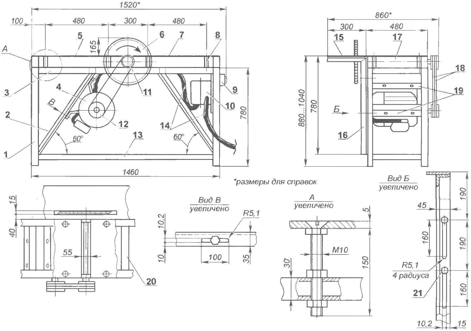
geometry and layout woodworking machine:
1 – front frame (area 45×45, 4 units ); 2 brace (area 35×35, 4 pieces); 3 — top rail (tube 60×30); 4 three-phase motor (N = 4.5 kW, n = 3000 rpm); 5 — receiving portion to the planer table (sheet s5); 6 – – O450 the saw blade (or cutting emery wheel): 7 — part infeed planing table (sheet s5) 8 adjustable support table (bolt with three nuts M10, 8 pieces); 9 – button station; 10 – a box of capacitors; 11 – the slave pulley; 12 — drive pulley; 13 — the bottom rail of the frame (tube 60×30); 14 cables; 15 lifting and sawing table (sheet s5); 16 subframe sawing table (area 45×45, 2); 17 – rotor plane; 18 V-belts (profile B, 2); 19 – rails (steel strip 455x50x10, 2 PCs); 20 — upper tie bar (tube 60×30, 2); 21 – bolt M10 mounting sub-frame lifting table (4 pieces)
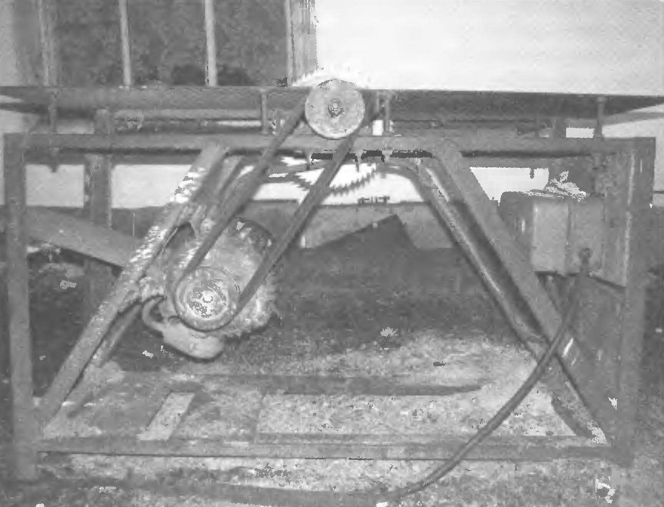
machine Drive (protective shroud removed)
From the right side to the posts of the frame are attached by two M10 bolts of the l-shaped bracket, made of the same area, and racks. The top (shelf) brackets serve as supports, lifting of the desktop. His plate is cut a groove for the saw blade (cutting or grinding).
Rack bracket is made of longitudinal grooves that allow you to lift the rack (with a plate sawing table) and make the “departure” of the saw blade above the table surface (approximately 160 mm and is almost to 0).
The other two parts of the table side (feed and receiving) is mounted on the frame on adjustable supports. As supports used a long M10 bolts with countersunk heads and with nuts and lock nuts. Using supports adjustable cutting depth (stroganyj) lumber.
The main site of the machine — operating shaft with a rotary planer and a saw blade.
The shaft is mounted in two bearings No. 80305. Bearings with housings are used from the thrown kolkhoz-sovkhoz agricultural machinery. The shaft is machined from steel 45 and the rotor plane is made of aluminum. Subsequently, the rotor on the shaft planted in tight hot fit without the dowels and pins. These details are given for revision to experts: on the shaft they are polished Seating surface and the rotor has longitudinal grooves profesionali under the knife.
The rotor of the three-knife planer. Knives with double-sided blades are made from tool high-speed steel R18. In the grooves of the rotor they are fixed by M6 screws through clamp bars.
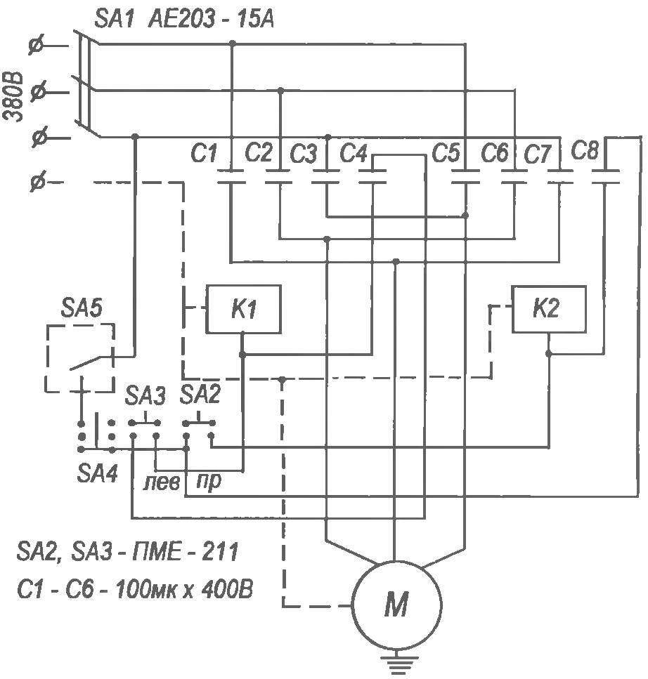
Electrical control circuit and enable the motor of the machine
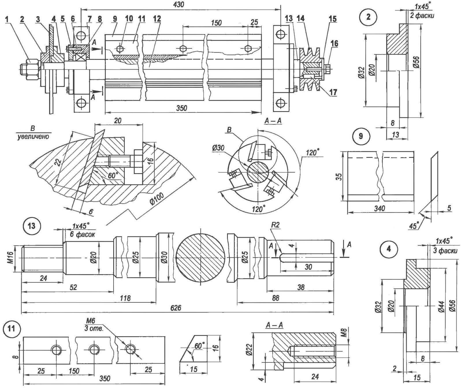
worker node:
1 — nut M16 (fine) spring washer; 2— clamping flange (St3, the circle 80); 3 — circular saw (purchased the product); 4 — bore flange (St3, the circle 80); 5 — cover housing bearing (farm equipment, 2); 6 — M6 screws (8 PCs); 7 — the bearing housing (agricultural machinery 2); 8 — the bearing 205 (purchased product, 2); 9 – the knife (instrumental steel R18, 3 pieces); 10 — spacer screw M6 (9 PCs); 11 — clamping strip (ST5, 3 pieces); 12 — rotor (made of anodized aluminum, round 100); 13 — the working shaft (steel 45, range 30); 14 — double-strand-driven pulley (duralumin from the cutting machine); 15 — pressure washer (St3, circle 52); 16 — screw M6 spring washer; 17 — key (St3)
Before Assembly, the worker node the specialists have adjusted the relevant parts (blades, screws and straps) by weight, and after Assembly, carefully balanced node: although the rotor diameter is small, but the speed is such that even a slight imbalance would cause a big vibration.
Double-strand pulleys with V-belt drive transmission — dural profile streams under the belts of type B. They were picked up finished by some of the old cutting machine. The diameter of the driven pulley is slightly smaller than the diameter of the lead — therefore, the rotation of the rotor of the planer and the saw blade slightly higher angular velocity of the motor, that is a little more than 3000 rpm.
The circular saw is always in the yard on the plot. Therefore, in order to avoid its unauthorized inclusion of grandson in addition to the circuit breaker in the electrical panel and push button station equipped on the frame machine more “key lock” is an extra, hidden, switch. Working bodies in working condition circular saw metal close the top cover upside — down old steel trough, attaching it at the corners to the plates with bolts.
In the wiring diagram of the machine provided for reverse (backward) rotation of the engine (and thus the working shaft). For a plane it is not necessary, but for the saw blade and an emery cut-off wheel, such rotation is sometimes nice — for the convenience of the machine.
V. KURAKIN
Recommend to read
 BMW 645Ci Volga
Design domestic car GAZ-21 "Volga" is haunted by the many fans of this car. Some create precise scale models-copies of this iconic sedan. Others meticulously and carefully recreate the...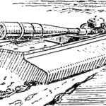 “SALAMANDER” CLASS FSR
Today we offer RC modelers a high-speed hydroplane races for long, designed and built by famous Hungarian athlete Istvan of Salim. "Salamander" — the so-called new microtiter — has a...
