Further according to the method pocherpnut from the article “Sprocket for chain transmission” in No. 11 for 1975 of the journal “modelist-Konstruktor”, I made from a suitable steel 12ХНЗА four stars, but with the number of teeth 11 and step 15,875 mm. working surface had to be solid and durable, so I used cementing and thermal annealing.
Securing two such stars at the end of the output shaft of the worm gearbox and two on the start shaft, I tied them two Bush roller chains. This branch of the chain transmission can be called secondary. To her relief used a thin metal lining under the gearbox, and for the protection against pollution, solid casing casing chassis.
Power platform:
1,6 — sleeve of fastening of racks of the chassis (steel 45); 2,4,5 — ribs (area 30x30x4); 3 — platform (steel 45, the sheet s8)
Motor cultivator (starter ST-8 with electronification in the same casing):
1 —fan shroud (Д16АМО, sheet s2); 2 — fan motor (brand MAE-7B, the ZIL-164); 3 — hub of the impeller with nut; 4 — the block of the blades of the impeller of the fan; 5 — a bolt М5х20; 6 — back cover housing-starter (regular, modified); 7 — clamp (Д16АМО, strip 20×2); 8— standard sleeve bearing (bronze); 9— casing of the starter; 10 — pinch bolt M6 (2 PCs); 11 — rotor of starter; 12 — remote bushing (brass LS59-1); 13 — front cover of the starter housing (ДІ6ТВ); 14—bearing 204; 15 — block star-hub; 16— a bolt М8х35; 17,20— M5 bolts (8 PCs.); 18 — spacer (Д16АМО, strip 20×2, 4 valves); 19 — bandage (Д16АМО, strip 20×2)
Modified rear cap starter housing (cap oiler not shown)
The fan impeller (blades have not bent):
1 — hub (St3); 2 — the block of the blades (Д16АМО, sheet s1); 3 — nut М16х 1,5
Block star-hub:
1 — sprocket (z = 15, t = 12,7; from motorcycles K-125); 2 — hub (St3)
Cheek casing chassis Assembly:
1 — cheek (Д16ТВ, the sheet s8); 2 — rivet (D16, d6, 4x); 3 — bracket (Д16ТВ, angle 30x30x4)
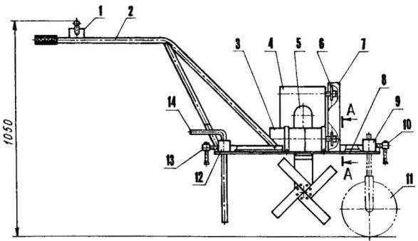
Suspension (in a side view of the working shaft is conventionally rotated around its axis by 45°):
1 —bolt М6х20 (16 PCs); 2 — blade left-hand cultivator cutter (St3, strip 45×6, 4 pieces); 3—bolt М6х53 (2); 4 — hub (30KHGSA, 2); 5 — working shaft (30KHGSA);6 — bearing housing (Д16ГВ, 2); 7 — wing М5х10 (8 pieces); 8 — casing of the casing (Д16АМ0, sheet B2); 9—way star (12KHN3A, just 4 PCs.); 10 — pin d8 (2); 11 — cheek casing (Д16ТВ, the sheet s8,2); 12 — bearing 206 (2); 13 — oil seal (felt, s3, 2); 14—remote Bush (Д16ТВ, 2); 15 — Bush roller chain (t = 15,875 mm, 2 pieces); 16 — screw М4х8 (24 PCs); 17 — the right blade cultivator cutter (St3, strip 45×6,4 PCs.)
The front landing gear:
1 — pin mount (St3, rod d18); 2— tire (from the wheel of children’s bike, 2); 3 — wheel hub (Д16ТВ); 4 plug (St3, strip 40×4); 5 — axis (St3, rod d16); 6— nut M 10 (2); 7 — remote Bush (St3, 2); 8— 160200 bearing (2 PCs.)
Lubricated chain when working in the so-called oil bath in a volume of transmission oil filled in the casing of the chassis. At the bottom of the casing rotates in two bearings 206, hidden in housings with felt seals, the working shaft carrying the cultivator cutter.
All of these units I have installed on the force platform, made of sheet steel and reinforced by welded longitudinal ribs of the steel area. Edges bolts M6 attached control knob electrocorticogram. Last welded from lengths of steel pipe. Two rear ends of the pipes put on a rubber arm that keeps the operator; four front end tapered and drilled holes in them under the bolts.
To move the machine manually for short distances, I made him a removable chassis, consisting of two racks. The front Desk has one double busbar feeders wheel (homemade, with tires from a child’s Bicycle), the rear two wheels (from a child’s Bicycle is bigger). Attached to the rack in a special bushing that is welded to the platform in front and behind, retaining (strubtsinku) screws.
On the edge of the field, before processing the soil, I reach for my electrochlorinator both racks. Instead of the rear insert so called brake pin and stopper it strubiny screw. Penetration of the pin into the ground adjust the speed and depth of cultivation.
Due to the fact that the unit I have is so light, depth of cultivation had first been insufficient. Had to weigh it down removable ballast weight of 20 kg, which were placed in the center of gravity of the machine. This gave the ability to withstand depths of 160-190 mm in the capture of cutters strip of land with a width of 250 mm. Productivity when working with my electrocorticogram the same as with the Mole.
As a power supply unit for starter ST-8 and the engine DOE-7B fan it would be possible to apply the welding transformer, however it is quite expensive. So I went the other way. Took three low-power (about 500 watts) of the transformer, removed the secondary winding and on the vacant seats wrapped around the tire, the cross-sectional area of which is 25 mm2 ; then the primary (AC — 220V) winding connected in parallel, and the secondary (4-5 In each) — in series-according to. As a result, the output transformers turned the AC voltage of 14-15, which is then rectified by bridge diode VK-200 (replacing the diodes of this brand possible any other with a current of 200 A, which is very convenient).
Rear landing gear:
1 — pin mount (St3, rod d18); 2 brace (STZ, rod d10, 2); 3 — axis (St3, rod d25); 4— wheel (odeskogo bike, 2 PCs.)
Electrical schematic engine power cultivator
Control handle cultivator (steel, pipe 30×2)
Brake pins (St3, rod d18)
Power supply unit I have was pretty heavy and had to mount it on a separate four-wheeled cart. With a network socket on 220 In it is connected by forty-meter cable, conductor cross-section of 2.5 mm2 , with a cultivator — double (25×2 mm2 ) welding cable with a length of 12 m.
For supplying constant voltage to 14-15 In the starter I used a standard packet switch (25 A, 250 V) with a long handle, in which “aparallel” three power lines. Switch placed on the left handle control of the cultivator.
Thus, due to the application of the separation of stepdown transformers on 220/14 managed to ensure complete safety from electric shock while working with the cultivator even on wet soil (of course, in strict compliance with other safety requirements).
Electrochlorinator fully lived up to my expectations. Now, consider the four seasons I effortlessly treated with it, their entire infield.
V. LEBEDEV, Dolgoprudny, Moscow region
Recommend to read EXACT HIT Determining the place in the door jamb to nest under the lock bolt, cut out a paper rectangle, the shape is equal to the end of the bolt. Moistened with water one side of this rectangle,... ALFA ROMEO 6C 2500 SS A company called Anonima Lombarda Fabbrica Automobili. which subsequently became the acronym ALFA, was established in June 1910. First released it the car had a high speed, power and...
 The owners of the garden plots are very popular cultivators “the Mole” with petrol engines. At first I was extremely happy with his mechanical assistant. However, over time, decided to get rid of the noise and noxious exhaust of a gasoline engine and make environmentally friendly electrochlorinator, safe from shock. For the cultivator required a motor with a serial excitation, which increases as the load increases and the torque. More other ideal starter stamps ST-8 from the truck GAZ-51.