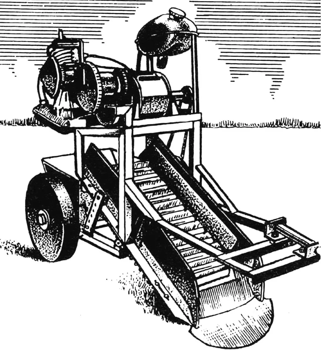
The structure I’m going to talk about could be called a potato harvester, as it consists of several relatively independent units.
The potato digger is designed primarily for coupling with the mini-tractor “Osorinets”, described in “Modelist-Konstruktor” No. 12, 1996. But since it has an autonomous engine, it can work in tandem with any tractor regardless of whether it has a power take-off shaft or not. You can even harness a horse! I think the basic design of my harvesting machine will be useful to other amateur constructors creating their own agricultural equipment.
The feature of the design is this. Moving behind the mini-tractor along the inter-row spaces, the trailed unit lifts the ridge (row of potatoes) with its shovel-shaped share and releases the tubers. Together with soil and remnants of tops, they fall onto the chain-and-rod conveyor of the elevator. In other potato diggers, the tubers are directed from the conveyor through a passage chute into a cleaning drum, where they constantly accumulate at the entrance, delaying harvesting. In mine, there is no cleaning drum—the soil falls through the rods already on the conveyor, withered tops don’t create much interference, and the cleaned tubers end up in the storage hopper.
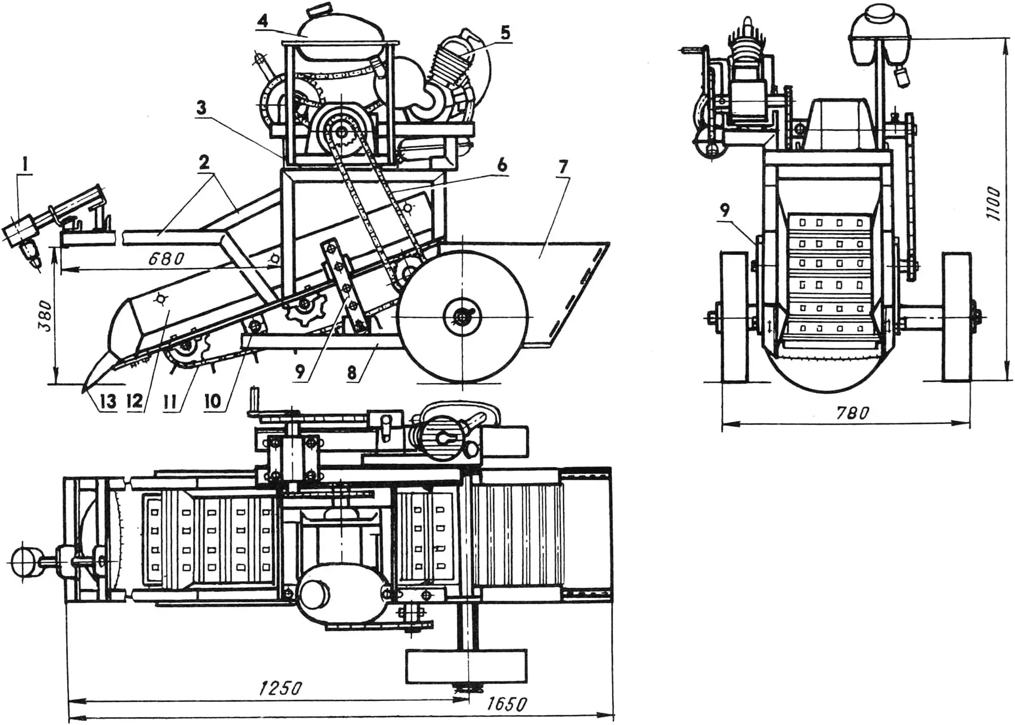
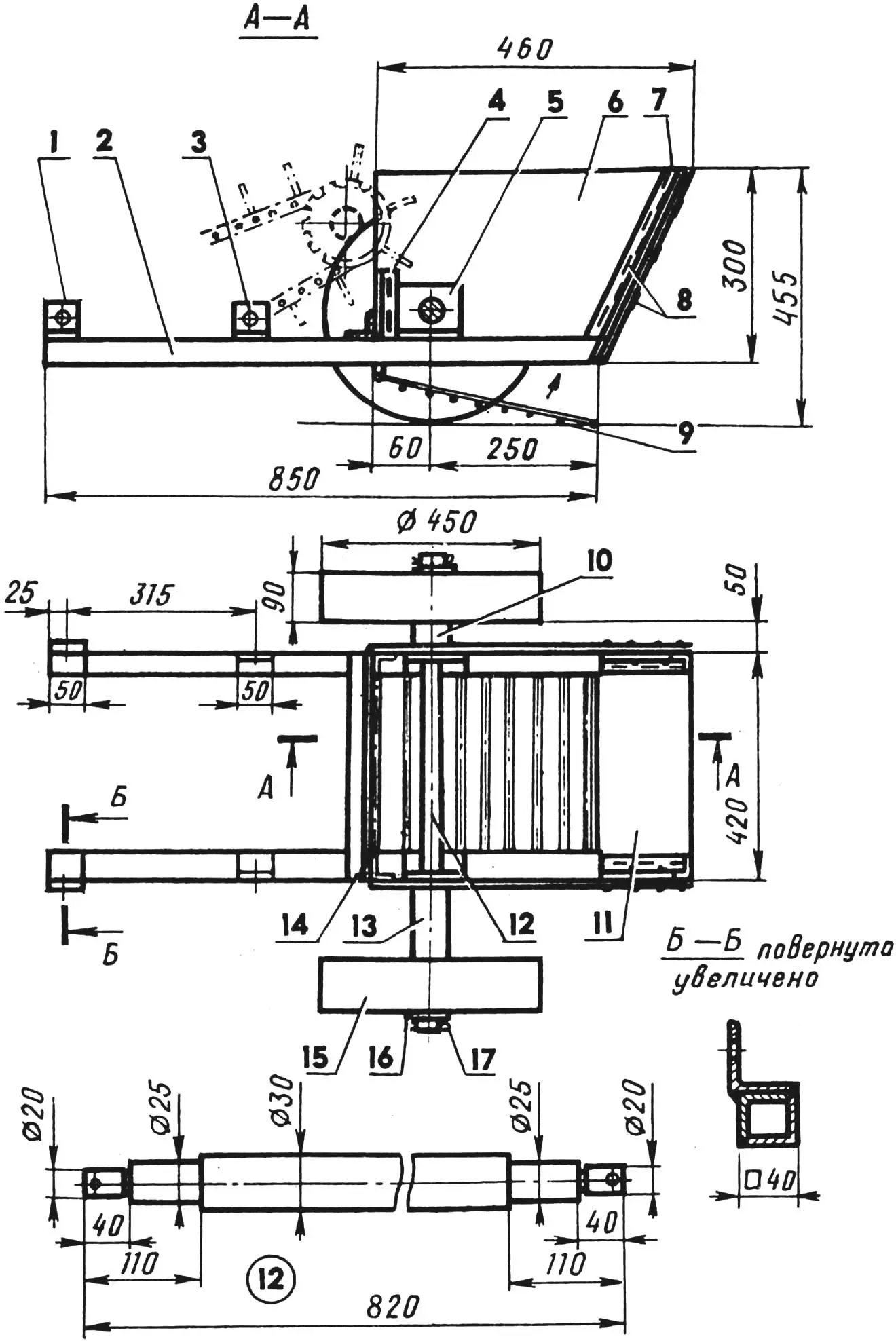
1,2 — hinge and links of the coupling device (not shown on front view), 3 — motor-reducer block frame, 4 — fuel tank, 5 — engine, 6 — elevator conveyor drive chain, 7 — storage hopper, 8 — wheeled carriage, 9 — adjustment bars, 10 — elevator mounting unit, 11 — chain-and-rod conveyor, 12— elevator side, 13 — share.
The harvester is simple in design—it contains many units and parts from decommissioned agricultural equipment, primarily from an industrial potato digger, and also technologically—for its manufacture in a home workshop, it’s enough to have a hacksaw, electric drill, and welding machine (lathe work here is minimal).
The kinematics are based on three chain drives and one chain-and-rod drive (using roller chains and sprockets from mopeds, bicycles, and agricultural machinery).
Now let’s go into more detail about each of the main units.
The main one is the elevator. It performs two functions: transport—moves and cleans potatoes—and load-bearing—the entire motor-reducer block is attached to its frame. The elevator is installed asymmetrically relative to the wheeled carriage. This is related to the peculiarity of the tractor’s operation—the width of its track is usually greater than the distance between ridges, so some wheels of the tractor and carriage always travel along the inter-row space, while others travel along the harvested field.
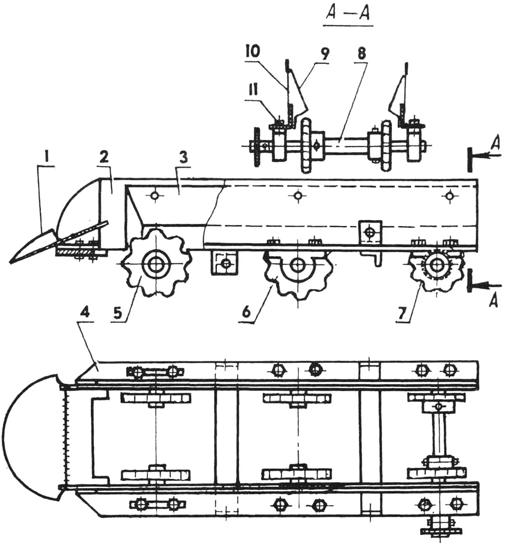
1 — share, 2,10 — sides, 3, 9 — chutes, 4 — frame, 5 adjustable support sprocket (z=9, 2 pcs.), 6 — non-adjustable support sprocket (z=9, 2 pcs.), 7 — non-adjustable drive sprocket (z=9, 2 pcs.), 8 — drive shaft, 11 — bolt M10 (16 pcs.).
The elevator frame is made from 45×45 mm angles. The share and housings of support and drive sprockets on the conveyor’s drive shaft are attached to it.
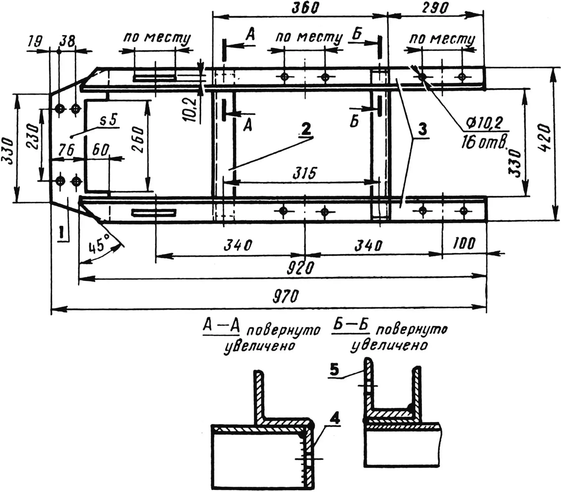
1 — front part (steel sheet, s5), 2 — cross member (angle 45x45x5, 2 pcs.), 3 — side members (angle 45x45x5), 4 — carriage mounting bracket (steel sheet, s5, 2 pcs.), 5 — adjustment bar bracket (angle 45x45x5, 2 pcs.).
The chain-and-rod conveyor or track—from a decommissioned potato harvester. Its chains are shortened to approximately 1670 mm (44 rods left), and the rods—to 300 mm. The track is equipped with tuber capture blades (without them, large potatoes will roll down) and installed on support sprockets, the front ones being adjustable (they determine the chain tension). The conveyor moves via drive sprockets on the drive shaft. Moreover, at a speed greater than the tractor’s speed along the inter-row space, otherwise the harvester won’t handle the flow of incoming tubers.
1 — roller chain, 2 — blades, 3 — metal bushing, 4 — axle (shortened rod), 5 — plastic bushing.
1 — drive sprocket (z=19), 2 — frame side member, 3 — drive sprocket, 4 — bolt M8 (3 pcs.), 5 — drive shaft, 6 — bearing 204 in housing (2 pcs.), 7 — lock washer (4 pcs.).
Sides made of 1 mm thick sheet steel are welded to the frame angles, and chutes covering the chains are attached to the sides so potatoes don’t get into them, plus four brackets: two for bars that adjust the tilt angle relative to the wheeled carriage, and two—for mounting the elevator to the carriage.
As mentioned above, the motor-reducer block with its frame is attached to the elevator. The engine is a moped engine, D-6, without any modifications (though it would be useful to install a forced cooling fan). Its power is more than sufficient to drive the conveyor. It starts in the simplest way—with a starting lever. Hand force is quite enough for this.
1 — block frame, 2,9 — large sprockets (z=48) with bushings, 3, 7 — small sprockets (z=16) with bushings, 4 — engine, 5,6 — upper and lower shaft housings with bearings (from agricultural machinery), 8 — engine frame, 10 — moped chains, 11 — engine manual start lever.
The reducer is a combination of three chain drives (all chains are moped chains, and sprockets are bicycle sprockets, modified) and two intermediate shafts—upper and lower. The reducer’s purpose is to transmit torque from the D-6 to the elevator’s drive shaft.
1 — left post, 2 — rear bracket, 3 — front bracket, 4 — lower cross member (2 pcs.), 5 — upper cross member (2 pcs.), 6 — right post, 7 — upper supports (2 pcs.), 8 — engine frame platform (steel, sheet, s3), 9 — lower supports (steel angle 50x50x3, 2 pcs.). Parts 1 — 7 from steel angle 40x40x3. All mounting slots are made in place.
Fuel flows by gravity from the fuel tank installed slightly above the engine.
The cargo block is also structurally simple. It consists of a wheeled carriage and a storage hopper. The carriage frame is welded from 40×40 mm angles, and the hopper walls are cut from roofing iron and attached to the front and rear posts with thick wire through special holes (such fastening is quite sufficient; using bolts or rivets here seemed impractical to me). To unload the hopper, the grid bottom is lowered, and the tubers are collected into pre-prepared bags.
1 — elevator mounting bracket (angle 45x45x5, 2 pcs.), 2 — longitudinal beam (angle 40x40x4, 4 pcs.), 3 — adjustment bar bracket (angle 45x45x5, 2 pcs.), 4 — hopper front post (angle 20x20x3, 2 pcs.), 5 — wheel shaft bracket (angle 63x40x8, 2 pcs.), 6,11 — side (2 pcs.) and rear hopper sides (steel sheet, s0,8), 7 — hopper rear post (angle 20x20x3, 2 pcs.), 8 — side fastening (steel wire Ø 3), 9 — hinged bottom (steel rod Ø 10), 10,13 — short and long spacer bushings (steel tube 37×3), 12 — wheel shaft, 14 — cross beam (angle 40x40x4), 15 — wheel (from agricultural machinery, 2 pcs.), 16 — washer (2 pcs.), 17 — cotter pin (2 pcs.).
The share is made from four parts: a cut cultivator disk, a 4 mm thick steel plate whose front edge is hammered to match the disk shape, and two brackets from 45×45 mm angles. The disk steel is hardened; it’s not afraid of stones or dried clods of earth. The semicircular shape of the cutting edge is most effective when digging potatoes. The share is attached to the elevator frame with four bolts.
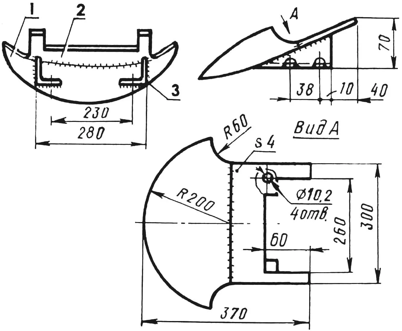
1 — cut cultivator disk, 2 — base (steel sheet, s4), 3 — bracket (angle 45x45x5, 2 pcs.).
I won’t specifically describe the coupling device. Everyone’s equipment is different, and mounted implements are usually attached differently. I’ll just say that the leading element of the unit is a hinge from a truck’s steering link—a convenient and reliable part.
The potato harvester has been in operation for two seasons now and has significantly reduced the burden of agricultural work for our family.
S. GORYACHEV
Recommend to read
 DOUBLE BED
When the family of two children — and doubled. For instance, bedrooms require more space under them. That would let the industry such as baby beds that day took place less than half the... COFFEE — FROM THE CHAIR
Old chair caught for one reason or another are unnecessary, can be turned into a small coffee table. For this you will need chipboard for the table top and a few screws.
