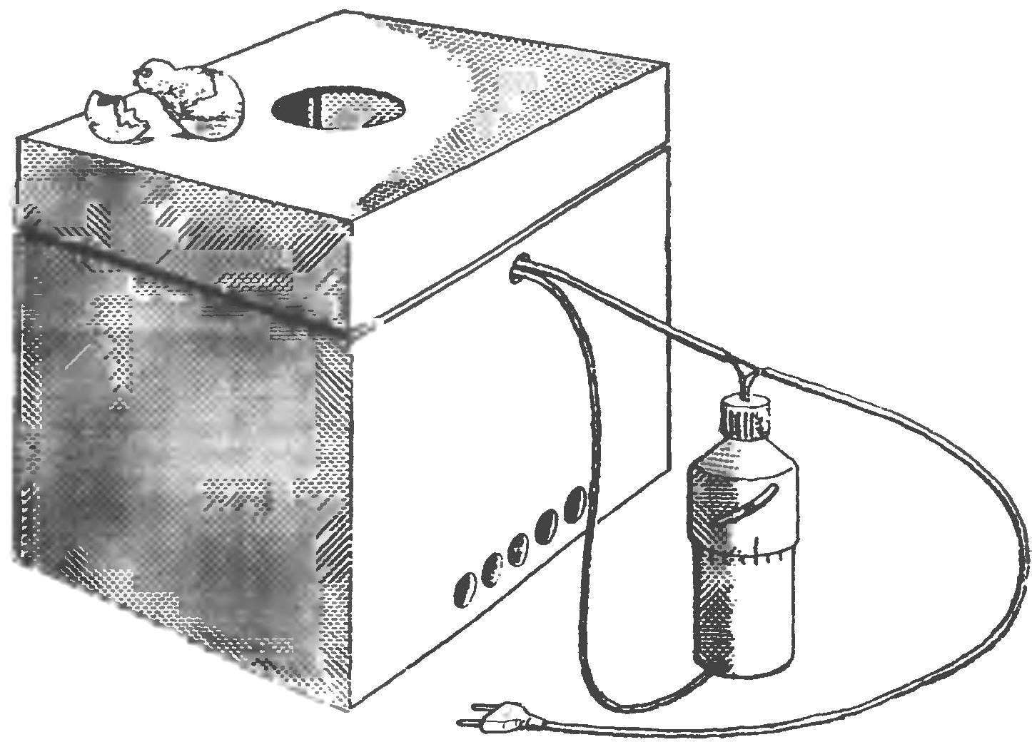

 This simple incubator can become a reliable assistant in every household, it will save you from annoying spring and the worries associated with the acquisition of their farms for chickens. This instrument is as simple to manufacture as in operation. The idea of this incubator belongs to reader “M-K” V. Sopeno of the Belgorod region, the design study laboratory “Eureka.” Keeping the author’s idea, we have tried to make the device more reliable and safe.
Take a look at the General arrangement drawing of the incubator. As can be seen from it, the centerpiece of the device is a three-liter Bank — it is a kind of heat generator and a heat accumulator at the same time. Of course, the water in it to warm up, and this can be done using any domestic boiler — best of the smallest, with a capacity of 300 — 400 watts. Attached to the boiler Bank by using a bracket and clamp cut from any metal sheet thickness 2 — 3 mm. the Shape and dimensions of the bracket shown in our drawings; the dimensions of the clamp are chosen depending on the dimensions of a holder of a boiler. Fixation of the clamp on the bracket by a pair of screws M4 with nuts. The bracket attached to the standard plastic lid (such Housewives used for home canning) with a pair of M4 screws with nuts and washers. Inside and outside cover under the steel washer be sure to enclose the rubber washers seal as the cap Bank and needs to connect completely sealed.
In addition to the bracket of the boiler, on the lid are fixed two contact terminal studs M4 (each with four nuts, two metal and two rubber sealing washers), through which voltage is applied to the boiler.
And the last one is passed through the lid of the metal tube that reaches almost to the bottom of the jar. To secure such a tube, it fits over the cut pipe with a larger diameter thread on the outer surface, after which the joints propisyvayutsya. The tube is fixed to the cover by a pair of nuts, and two metal and two rubber washers.
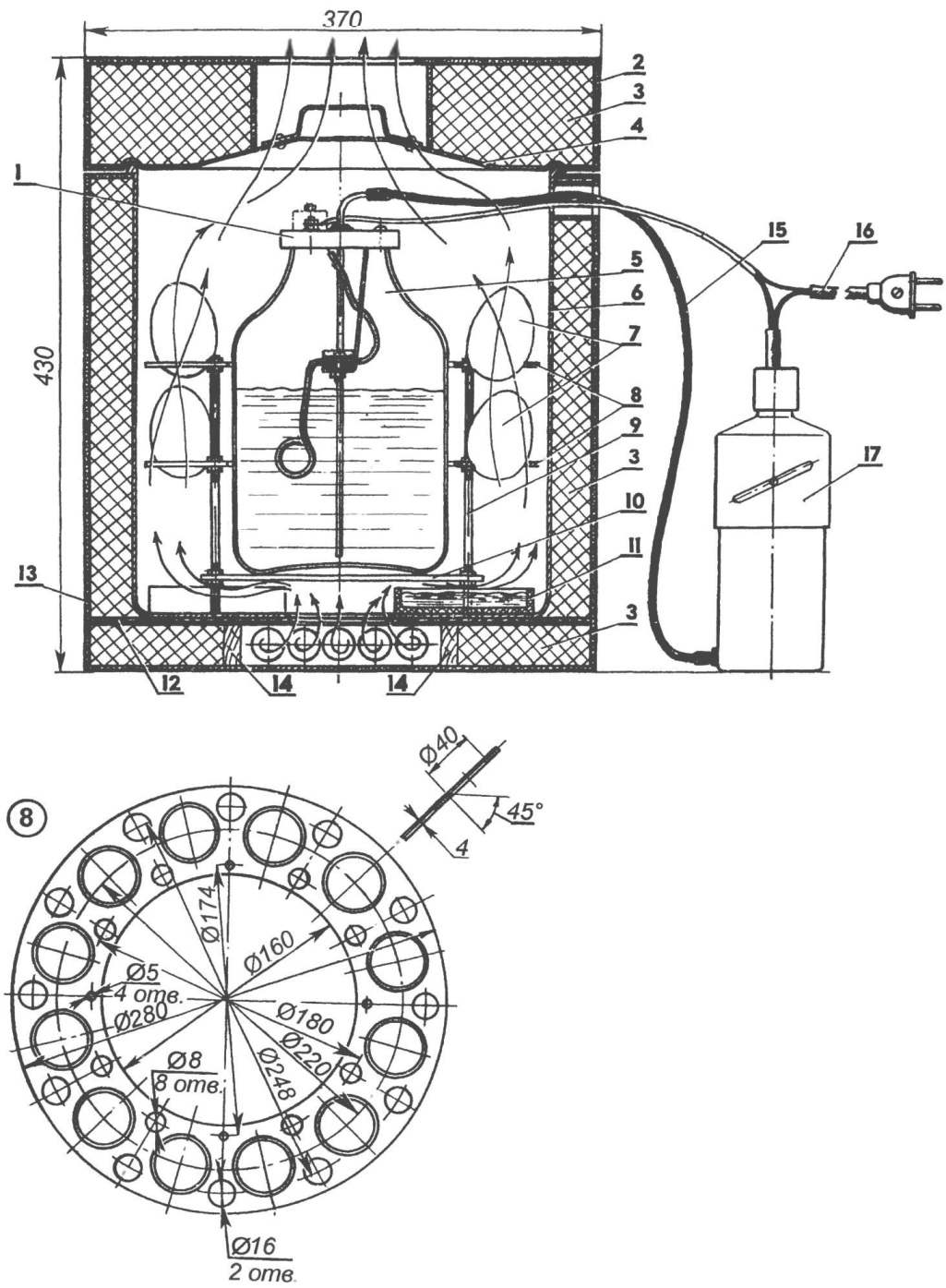
Fig. 1. Incubator:
1 — cap banks-heat (complete with boiler and water-tube tion); 2 — the cover of the casing of the incubator (plywood, hardboard, or corrugated cardboard); 3 — insulator (foam, sawdust or straw chaff); 4 — housing cover of the incubator (cover the pan); 5 — Bank heat capacity 3 l; 6 — the case of the incubator (aluminum pan); 7 eggs; 8 — lodgements under the eggs (plywood or organic glass, s3…4); 9 — front (steel pin M5 4 pieces); 10 — pallet (plywood or plastic disc Ø200; s4…5); 11 — water tank (4 pieces); 12 — partition (plywood s4); 13 — cover of the incubator (plywood, hardboard, or corrugated cardboard); 14 — the wall of the ventilation channel (Reiki 12×30); 15 — connecting tube (rubber or vinyl tube Ø4…5); 16 — power cord with plug; 17 — heat regulator
And one of the main components of the incubator — heat regulator. He also improvised and consists of a plastic housing, within which is located a plastics bottle float.
Body heat regulator compound, it is assembled from two pieces cut from the bottles, packaging of detergents. Please note that the upper part, with a small gap is placed on bottom. On the lateral surface of the upper part of the lid are cut two helical groove, which allows you to smoothly move relative to the bottom of to adjust the moment of actuation of the thermal regulator In the mouth of the makeshift cover fixed limit switch. His body turned from any insulator (e.g., PCB or Plexiglas); the side contact screws with thread M3, it is desirable to use copper or brass, of the same materials and the Central contact screw with M4 thread. The latter screwed into the pusher, also carved out of any insulating material.
In the lower part of the body of heat regulator fixed bulkhead fitting, assembled with the aid of the soldering of two copper pipes — external thread M8 on its outer surface, and an inner diameter 5×0,5 mm.
Inside the housing is a float — plastic bottle, the diameter of which should be such as to ensure desyatiballnoy the gap between the inner diameter of the lower part of the housing and the float.
Now you can make a trial Assembly to verify instrument operability.
For a start the Bank heat source is two-thirds filled with water and it is densely planted cover Assembly. Next, using a rubber or polyvinyl tube fitting on the body heat of the regulator connects to the fitting on the lid of the jar-heat source. The boiler also connected to the network via the contacts of the limit switch, which initially are in a normally closed condition.
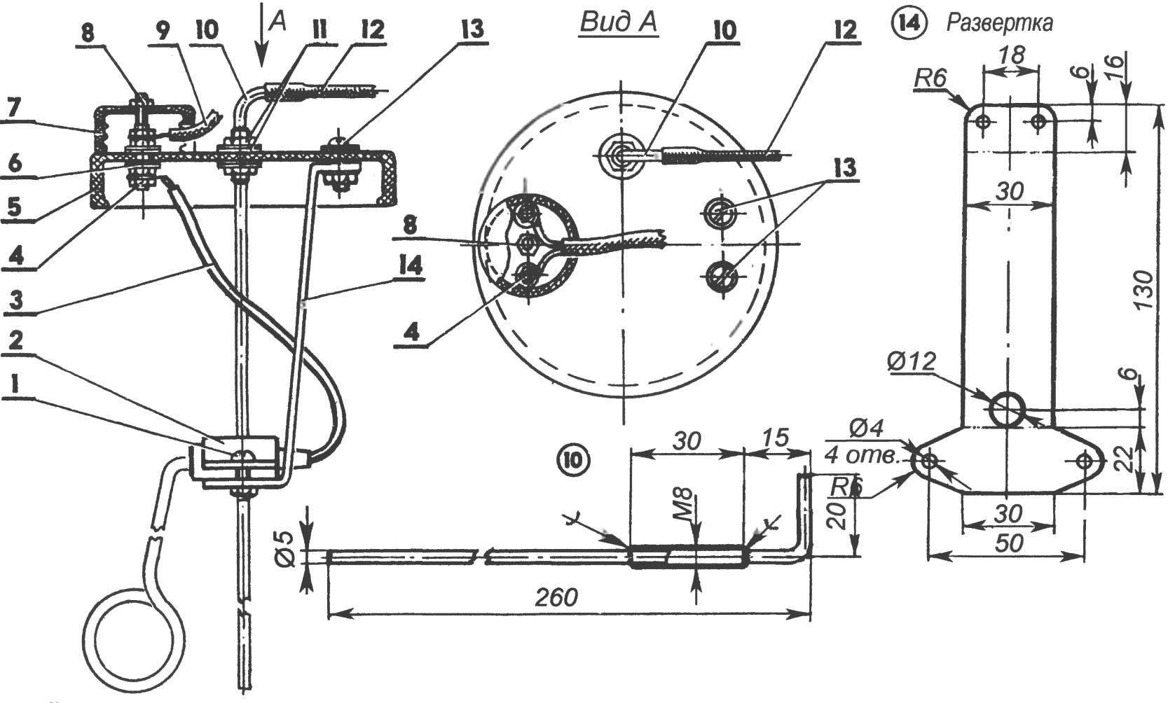
Fig. 2. Cap banks-the heat source:
1 — M4 screw with nut; 2 — a clamp (steel or aluminum s2…3); 3 — the power cord of kettle; 4 — terminals (threaded studs M4 with nuts and washers); 5 — plastic cover; 6 — washer-gasket (rubber, 2); 7 — protective cap (plastic cap Ø30…40); 8 — fastening of the protective cap (screw the M4 nuts, washers and washer-seals); 9 — connecting cables; 10 — intake tube (going similarly to the parts 10 and 11 in Fig.3); 11 — fastening the intake pipe (M8 nut, washer and rubber washer seals); 12 — connecting hose (rubber or vinyl tube Ø4…4.5); 13 — bracket fixing (M4 screws with nuts, washers and rubber washers seal); 14 — bracket (steel sheet s2…3)
So, through the contacts of the thermal switch, the heater included in the network and begins to heat the water in the pot. Of course, heat and air, located above the water surface in the cavity of the jar. Because the Bank is closed tightly, increasing the pressure of the air begins to squeeze water from the banks intake tube into the housing of the heat regulator. The float rises and eventually touches the cap pusher limit switch, the circuit is broken. Next, the water in the pot begins to cool, and cools the air above its surface. Water from the body heat of the regulator is sucked back into the jar-heat. The float is lowered until then, until the limit switch again closes. The kettle once again begins to heat the water in the pot. Here is the whole complete cycle of operation of the heat generator.
Verify that the device you can start the final build of the incubator.
For the inner case of the incubator it is best to choose the aluminum pan is its internal diameter should be about 300 mm and a height of about 320 mm In the bottom and the lid of the pan nastelivaetsya a few holes with a diameter of 10 — 12 mm, through which the ventilation cavity of the incubator.
The pan is placed in the casing, which in the simplest case can be made of corrugated cardboard. However, it is better to make housing more durable materials such as plywood or hardboard.
The space between the housing and pan should be filled with any insulating material, packaging or construction foam, small shavings, sawdust or even straw chaff In the lower part of the casing provides the inlet ventilation duct, for example, as shown on the General arrangement drawing is performed by a pair of rods and sheet of plywood.
Fig. 3. Thermal controller:
1 — wire connection; 2 — the case of the limit switch (PCB, glass or other insulating material); 3 — cover of the limit switch; 4 — cover of heat of the regulator; 5 — the case of the heat regulator; 6 — guide pin (M4 screw and threaded sleeve); 7 — limiter lateral displacement of the float (steel wire Ø1…1,5); 8—float; 9 — nut, washer and rubber seal washers; 10 — nozzle (copper or brass tube 5×0,5); 11 —clutch (copper or brass); the 12 — center pin (brass or copper screw M4); 13 — lateral contacts (brass or copper screws with M3 washers); 14 — the pusher limit switch
Cover case is going exactly the same as the body, and of the same materials. In the Central part of the lid is pasted a ring of cardboard, forming the exhaust vent.
Lodgements under the eggs are cut from plywood or any plastic of thickness 3 to 4 mm. they are Fixed by means of four threaded studs on the plywood or plastic disk with a diameter of about 200 mm, as shown in the drawing. At the bottom of the pots-the hull there are four water tanks that allow you to maintain optimum humidity in the cavity of an incubator.
Gathering the incubator, we recommend you a few days to devote to the instrument setup. To do this, you should be armed with the usual medical thermometer, placing it in the area of the eggs. Ideally, it’s nice to have a hygrometer to control humidity. The source data for the following adjustments: a temperature in the range of 37.2° to 39.5°, humidity 55 — 70%. If the temperature inside the incubator is insufficient, you must move the controller cap up and to monitor the temperature in the incubator within one to two cycles of heating. At higher temperature, cover with limit switch goes down with subsequent temperature control. In the process to fine-tune the thermal relay is in its body can be calibrated, and further, when adjusting the temperature to be guided by experimental data of the temperature of the thermostat depending on the rotation angle of the lid of the thermal regulator.
In the case that the position of the float within the recommended temperature range does not disable “terminal”, it should be loaded using any bulk material — for example, dry sand.
Chicken eggs are located in the two locating blocks, a dozen in each. During incubation it is recommended to periodically (at least once a day) to flip the eggs, as it usually does, a mother hen. You should not fear that when you turn the eggs, temperature inside the incubator can drop — in natural conditions it happens all the time when the hen leaves the nest to at least a snack.
It should be noted that the incubator of this type is a kind of thermal battery. Therefore, he is not afraid of long interruptions in power supply — incubator-thermos for extended periods of time will keep the water temperature at the Bank permanent. Well, if electricity in your home to “pass out” for a long time, and it does not matter: it is enough to replace the Bank-other heat source, with a poured her hot water and a few hours of incubator will regularly function as a chicken hen. It is only necessary early in the process of debugging tool in any case to measure the temperature of the water in the Bank: immediately after the heat controller will switch off the boiler, the reserve tank should fill with water with the same temperature.
Recommend to read
 Folding workbench
I arrived at the design of this universal (as I believe) workbench — an essential work table for a home craftsman — after several years of technical creativity. I designed it based on my... Teen buggy
On the roads and cross-country tracks of Latvia, new sports microcars — buggies built at the republic’s Central Station for Young Technicians — have recently appeared. One of them, the...
