HARNESSED THE WINCH..

HARNESSED THE WINCH..
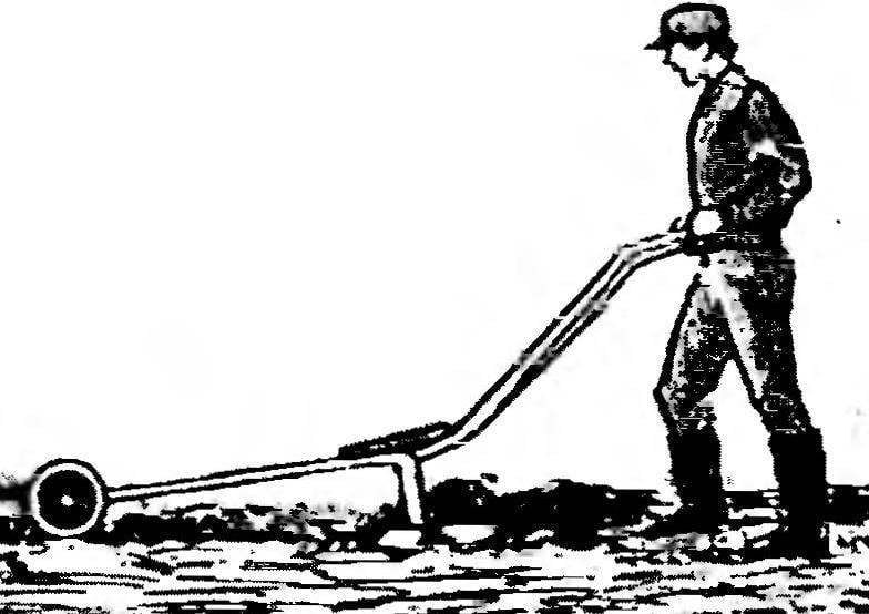
Winch, in combination with a plow, not news. Especially for owners of small plots of land on which these pretty simple and reliable konstruktsii a great way has already established itself. Unlike the mini-tractor winch not compacts the soil. And not stalled, as the tillers. But almost all traction motor power goes into useful work — plowing the earth towed plow. The winch is held securely in place by anchor legs which, with a kind of bayonet shovels, lengo deepened into the ground. Plowing are together, making a furrow for furrow. With a partner, the duties of which include the return of the plow n the beginning of the furrow may be 10-year-old child. High kachestvo spalni is guaranteed even at extremely inconvenient uchastkah (slopes with a profile like a “washboard”) and heavy soils.

We offer homemade plow-winch (see Fig.) has a number of additional benefits associated with the relative cheapness of electricity, ease of acquisition and long life (over 30 years) trouble free motor operation, ease of startup and operation the whole structure. The gear shift lever of the speed reducer is located in the immediate vicinity of the unit with the electrical equipment (capacitors, magnetic starter, push buttons “start” and “Stop”). Next — a roll of cable on a reel. So the winch can be anchored e anywhere on the land-I tion of the plot at a distance of up to 100 m by connecting it to the mains (with a larger cable length increases the loss in the line). And the existing design of the remote control with the “Stop” button allows you to control, keep plowing, working in tandem with the disabled.
 
When you hit the boulder or the roots of trees under the plow, the force on the rope increases dramatically. And when it becomes the maximum allowable (330 kgf), the electric motor of the winch is stopped, preventing the rope should break (as well as and breakage of the mechanism of chain transfer).
 
And one more feature. Thanks to the modular design with the electric winch if needed you can easily remove the motor unit with the electrical equipment (enough for it to Unscrew 4 bolts M10) and setting them on electrocapillary machine, to have firewood, shingles, timber, etc. Rearranging these nodes are the blocks on trevaresse, get valuable, vitamin-rich feed for livestock and poultry. Well, replacing a plow towed cultivator-Hiller, the same winch can be used not only for weeding-hilling, processing the rows, but, for example, for digging potatoes.
The kinematics? The proposed homemade design it is so elementary (and therefore reliable), which is unlikely to cause any difficulty when its “embodiment in metal.” From the motor shaft torque is transmitted (for this purpose a sleeve coupling) on the gearbox (taken from the moped “Riga” with further slight improvement). And from there (due to the transmission chain with a pitch of 12.7 mm) is on the drum of the winding on the last 10-mm nylon rope to the end of which is connected to the towed plow or cultivator-Hiller (aka digger).
 
In the base of the frame — welded construction of steel angle segments 34×50 mm with the tubular spar and brackets for mounting of motor, gearbox and drum. Moreover, the guide rail rope, made from an appropriately curved section of steel water-gas supply pipe 22×3, welded after installation of the drum. And in the last brackets provided for boring the holes for the shaft with the possibility of some displacement of the shaft to ensure proper tightness roller chains PR-a 12.7.
 
Plug on electricity
 
The plow on electricity:
1 — motor with Muff coupling shaft, 2 — unit equipment, 3 — anchor, 4 — frame, 5 — reducer, 6 — drum rope, 7 — power supply cable drum for storage, 8 — nylon rope, 9 — front part of the towed plow.
 
Frame electric winch
 
Frame electric winch:
1 — the frame welded (steel area 34×50 mm), 2 — the bracket under the motor (steel strip section 5×50 mm, 2 pieces), 3 — bracket left gear (steel area 34×50 mm), 4 — side rail upper (water-gas supply pipe 22×3), 5 — a gear bracket right (steel area 34×50 mm), 6 — bracket arcuate warney (water-gas supply pipe 22×3), 7 — arm drum detachable (6-mm steel sheet), 8 — bracket of the drum (6-mm steel sheet), 9 — the guide rope (water-gas supply pipe 22×3, welded after installation of the drum), 10 — a cross-bar (water-gas supply pipe 22×3), 11 — spar lower (steel area 34×50 mm, 2 PCs.), 12 — bolt M10 with nut, 3 PCs.), 13 — cosina (water-gas supply pipe 22×3).

 
Rope drum Assembly
Rope drum Assembly
 
The rope drum Assembly (chain PR-12,7 conventionally not shown):
1 — shaft (STZ), 2 — nut M16 (4x), 3 — washer (STZ, 4 PCs.), 4 — arm reel, 5 — bearing housing (STZ, 2), 6 — radial ball bearing (80204, 2), 7 — flange left (STZ), 8 — the drum housing (147-mm segment of the water-gas supply pipes 164×5), 9 — flange right (STZ), 10 — asterisk 2=64(66) (STZ), 11 — bracket of the drum is removable.
 
Design of the armature (the ends of
 
The design of the armature (the ends of “legs” is sharpened at an angle of 18 degrees).
 
The making of a sleeve coupling
 
Manufacturer of sleeve coupler:
1 — tube auxiliary (STZ), 2 — rod coupling (STZ); after drilling the hole 6 mm tube is removed and formed a semicircular groove chiseled square with a file under the key.


Static balancing of crankshaft rector
 
Static balancing of the crankshaft rector:
1 – line horizontal, 2 – crankshaft, 3 – weight balansirovochnye (trimming 8 mm steel wire).
 
A circuit connection diagram three-phase asynchronous motor electric winch in single-phase network
 
Schematic wiring diagram for three-phase asynchronous motor electric winch in single-phase network.
 
 
Towed plow:
1 — borozdna wheel, 2 — wheel field, a 3 — strut-beam (length of steel water-gas supply pipe 22×3), 4 — the reinforcement (steel rod <16 mm), 5 — arm (from strips of steel water-gas supply pipe 22×3), 6 — nolava Board (3 mm St45), 7 — shield-blade (from the body of the gas cylinder, high pressure), 8 — the crawler (angle steel 30×30 mm).

 
The design of the anchor is also welded (see Fig.). For its fastening to the frame of the electric winch (with the possibility of rotation on the axes of the bolts) holes are 10 mm. the “Feet” of the anchor are adjusted to then, when “swinging” alternate pressing right and left leg, they easy as a bayonet shovels, crashed into the ground, providing a reliable fixation of electric winch in the right place of the site.
 
The weld is completed and the drum. To install it on the shaft serve as bearings with shields or seals (number 80204 or, respectively, 180204). Housing — home-made, machined from steel billets (STZ). On the right is welded to the drum sprocket (z=64, t=12,7). Although the latter can have a number of teeth equal to 66, for reasons of technology (harvesting well installed in three-jaw Chuck of the lathe).
Towed plow is largely similar to the design published in No. 6 of the’90. In place of the expected maximum bending moment of welded steel rods with a diameter of 16 mm. In contrast to the plow-creep proposed by the author design with two handles, made as stand-beam, pipe 22×3 — steel water-gas supply. The blade-blade is a single cut from the steel body of the gas cylinder curved surface. So the need for a special plate made of hard alloy for the blade disappeared by itself. And the angle of attack of 6, found experimentally, largely contributed to the growth performance of the plow.
 
The role borozdna and field wheel can naturally be not only ready, taken, say, from a scrapped farm equipment, but improvised. The first in this case, it is welded from 5 mm steel sheet and the second sheet St3 thickness of 1.5 mm. Substantially the weight of the plow they are not • changed. And the latter is unlikely to be over the limit of 16 kg.
 
As previously stated, the motor is connected with gear coupling allowing for misalignment up to three degrees. The role of pin is used the M8 bolt that is inserted into a hole that is drilled in the clutch at the same time to the shaft. The bolt is screwed a nut, which is then immobilized as castellated.
 
In the absence of slotting machine the groove in the coupler under the keyway on the motor perform with… drill bit with a diameter of 6 mm and an auxiliary metal tube. The latter is then removed and formed in the coupling groove is adjusted to the required profile, four-sided file.
 
TECHNICAL CHARACTERISTICS OF PLOW-ELECTRIC WINCH
 
Dimensions during transportation (no s/s guns), mm ……………………………………….. 860x500x380
 
Weight with plow ng ……………………………………………………………………………… 76
 
The motor ……………………………………. asynchronous three phase are dust and water protected
 
……………………………………………………………………………….ispolnenii, “single-phase” inclusion
 
Power selectedvalues, NW ………………………………………………………………….. 1,5
 
Reducer …………………………………………………………. from moped “Riga”, gear ratio 37
 
The rotational speed of drum, Rev/min …………………………………………………………… 40
 
The average force on the rope during plowing, NGS…………………………………………….. 280
 
The power consumption when plowing one hundred kWh ………………………………….. 0,5
 
The working speed of the plough, m/s ………………………………………………………………………… 0,3
 
The capture of Coulter, cm ……………………………………………………………………………………….. 24
 
The depth of plowing, cm …………………………………………………………………………………… 25
 
The number of grooves on one permutation hoist, PCs…………………………………………… 3-5
 
The power supply voltage, …………………………………………………………………….220
 
Power supply cable ……………………………… hundred-meter twisted pair, with 1.5 mm2


As for the gearbox from a moped “Riga”, before installing in the design of the electric winch it is subjected to revision, with the elimination of all superfluous, not transmitting the torque of the parts. Removed, in particular, kickstarter, and the hole from it close rubber or aluminum tube with press fit. The clutch master and slave disks are welded together. The extra clutch disc throw. A block of gear teeth of the second gear are cut. This can significantly simplify management. Because the lever ‘enable gears are only “On” and
 
Crankshaft is better to carve a new shaft. But you can also use the fact that there— because of the difficulty in the manufacture in “home” conditions of slots for mounting a master disk of coupling. But then you have the old crankshaft carefully balanced. How?
 
Cut the rod near the shaft the latter is welded the balancing mass, which can successfully be cutting steel 8 mm wire. Then, taking a sanding disc excess weight achieve indifferent crankshaft position stowed, for example, on a strictly horizontal line.
 
Laid on the line of the crankshaft bearing seats. Do it carefully, reaching have static balance. Dynamic is performed “by eye”. At the same time trying to remove the excess mass with respect to the supports of bearings symmetrically to the transverse (bending shaft) moment was when the rotation is minimal.
 
As practice shows, after such a (mostly static) balancing vibration during operation of the reducer (and the whole electric winch in General) is not observed. But this, of course, does not exclude the use of other gear. Especially high-speed, worm pair in an aluminum casing. Only here is every homebrew will be able to find one? Not easier here confined to the old, “bargain” — from the same battered moped “Riga”.
 
The inclusion of the three-phase motor single-phase network for homebrew usually is not much difficulty. In our case this is the standard “triangle” with phase-shifting capacitors. The capacitance CP, expressed in microfarads, can be taken as 60 times greater than the motor power in kW. The value of the start capacitor is defined as triple the capacity of the worker, that is, SP= ZSR=Зх90 UF=300 UF. Achieve the desired value, connecting (in parallel) available under the rune of capacitors (e.g., type BGK-1) to the battery.
 
We also recommend you to use a small-sized electromagnetic actuator PME-011. But its coil is usually designed for connection to a network with voltage 380 V And we have 220 V. Therefore, a part of turns of the coil are removed.
 
For example, the starter coil, which we want to convert from 380 V To 220 V, contained 9000 turns. Then it is necessary to wind off enough to have left 9000:380×220=5200 turns.
Little modification is required to the “start” button. The second (usually normally closed to the factory version of the starter) the contact should be converted to normally open. This operation is performed quite easily, the benefit design allows.
 
And again. Control panel or at least one of the buttons “Stop” must be remote. Otherwise, the operator does not always have time to intervene and stop the motor, if suddenly the plow will be taken during plowing not stubbed rows boulder or root, and a winch as luck would be at this moment why something is loose (not too deeply stuck in the soil “feet” of the anchor).
 
As for the electric winch, it is easier to understand to understand all the nuances of using schematic diagram (see Fig.). When you click on the “start” button closes the corresponding pair of contacts in the coil circuit of the electromagnetic actuator. Actuating, the latter supplies the motor winding 220 (via the normally closed contacts of the Stop button, the contacts K1.1 — K1.4, the phase-shifting capacitor CP and SP). The motor starts and revs drum, winding on itself, the rope and starting to haul the plow.
 
But the operator releases the “start” button. Rasikas, БВ1 disables Bokovoy capacitor. The normal operation of the engine provides now only SR.
 
Clicking on any of. buttons “Stop” (control room or remote), the starter coil is de-energized. The contact 1.1 To 1.4 are disconnected. The motor stops. He de-energized due to actuation plavkova of fuse in case of overload arising from, say, maximum (330 kgf or more) effort on the rope while falling under the plow of the boulder or not stubbed rows of roots. The winch is disconnected from the mains supply also in the case when any abnormalities in the operation of the circuit will react to sensitive electronic equipment protection (e.g. type USES-10.2.01 ОУХЛ4 produced in Gomel), if such failed purchase and install the design (Fig. missing).
 
Finally, the last. Never neglect safety rules. After all, we are dealing with motor and equipment
 
tion with a voltage of 220 V. Especially if the winch is connected to the mains directly, without isolation transformer, with no electronic equipment protection. To use this technique in the ploughing is possible only in the form of exceptions to compliance with extreme caution. Work only means of protection from electric shock (special rubber shoes, rubber gloves, etc.). As fire to be afraid of rainy, wet weather.
 
Unacceptable use of wire rope instead of nylon rope. For greater security, you must only work together, but not alone. If there is even the slightest doubt about the strength of the rope, to avoid possible injuries in case of breakage it protect yourself and partner: you could at least wear protective (wire or lattice-type hockey) mask. As they say, better safe than sorry God himself protects.
 
V. RADKOV

Recommend to read

  • EGLOMISE: TOOL-UNIVERSALEGLOMISE: TOOL-UNIVERSAL
    The article "Acupuncture for metal", published in the journal "modelist-Konstruktor" No. 2, 1974, provoked numerous responses, not only individual readers, but also many businesses and...
  • MAGAZINE FOR KNIVESMAGAZINE FOR KNIVES
    Offer two wall-mounted design magazines for kitchen knives. The first consists of two wooden foils with a cut in one of them Windows. If you need to clean the grooves is sufficient to...