Thanks to the main transmission with differential locking is possible individually by either right-wing or left-wing wheels and, consequently, rotate in one direction or another. The lock is handle with belt slip with friction discs: clinging to the disk, it slows down the rotation of the axle shaft. The crank is bent from the pipe: it can be rotated on an axis fixed in the angled console frame. At the end it is welded to the base plate under the cleat — cut drive belt, fastened through it and the pipe with two bolts. Many believe that if the clutch to put down the tape, completely encircling the pulley, the braking will be more effective. However, as practice has shown, it is enough to touch the disc in one place. Tape often “prihvatyvaet”.
Wheel put on the axle shafts resting on bearings. On the one hand these buildings are the wheels, the other driven sprocket ( Z = 20). Due to the fact that the leading — on the shaft of the intermediate gear drives posted, comes in different planes to put the followers. It made to make the bearing housings (and therefore axle) different lengths: front — 110mm, and the rear is 85 mm. the Extra tension of the chains is absent here: helps adequate coverage of the sprocket. If the chain stretches over time, it is only necessary to shorten them to remove a few links. Thus, in the whole of the transmission is regulated only by the circuit from the output shaft of the engine.
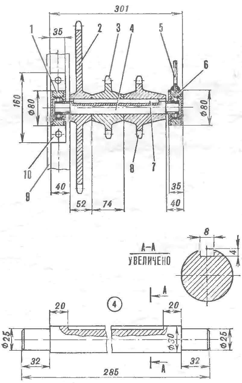
Fig. 5. Intermediate shaft:
1 — housing of the outer bearing 2 and driven sprocket Z = 54, 3 — star, rear wheel drive Z =13, 4 an intermediate shaft, 5 — console 6 — case inner bearing, 7 — shaft key 7X8X181, 8 — peredney drive sprocket wheel Z = 13, 9 — strength steel frame, 10 — top cushion supports (the bearing housings are identical).
Fig. 6. Kinematics:
1 — engine, 2 — bearing housing front wheel, 3 is the intermediate shaft bearing, 4 — bearing axle main transmission, 5 — body rear wheel bearings, 6 — housing of the main transmission, 7 — the axis of the main transmission (step all stars 19,05 mm).
Fig. 7. Axle Assembly (front wheel, B — rear):
1 — axis, 2 — front cover bearing housing, 3 bearing housing, 4 — back, 5 — Bush, 6 — sprocket Z =20, 7 — dowel 7Х8Х75, 8 — pin, 9 — spontaniczna puck.
Fig. 8. Rocker mounted equipment:
1 — front shoulder, 2 — arm rocker, 3 — shoulder guns, 4 — flange mounting guns, 5 — strength steel frame, 6 — axis arm, 7 — sleeve, 8 — bolt clamp.
The wheels are made of metal discs Ø600 mm and a thickness of 8 mm. On them on the circumference of the welded rings (70 mm) of the bands 6Х30Х200 mm: they make it easier to rotate and at the same time help to make sufficient traction — the wheels are not skidding even on the ice when cleaning snow, not “salted” and when working on wet ground.
Agricultural implement is hung on a yoke, passing under the frame of the mini-tractor. Cultivators, harrows, rakes usually have so that they had in the middle of the track. But with the plow harder. The point here is that the resistance of the plow when plowing turns the car’s wheels in this case are on the one hand in a furrow or the virgin, and on the other on the already plowed land. Therefore, depending on the operating conditions (density of soil, depth of plowing, etc.) necessary to move the plow. And how much is determined already, as they say, almost. To be able without much difficulty to move the plow, the yoke I put on the sleeve, which “goes” left to right across the frame on an axis. In heat fixing of the plough should be at the level of the wheel axles. Otherwise there is a turning moment in the vertical plane and the machine will “stand up” or, conversely, overloading the front end. One more thing. Obviously, the furrow when plowing should be deep throughout its length. But it is difficult to reach, moving all unevenness in the field!
On the “Kaluga” to provide an even plowing easier than for tractors with guns, hung directly on the norm, when any inclination of the machine affects the quality of the soil. My car suspension point of the rocker arm of the plow is located on the Central axis of the base, and it is not fixed in a vertical plane and can “swing”. So no, the trim does not affect the depth of the furrow — depth of the plow will be almost constant. Also in the center of the tractor suggest to set the seat — the driver will be much easier: less pitching. After all the “excitement” when driving over bumps and potholes quite considerably. The throttle, reverse, transmission, francione better to endure a little forward, but so that all was as it should be at hand. In this case, when the stretch “Plowman” from site to site and can “lead” him, stepping after him.
V. ARKHIPOV, Kaluga
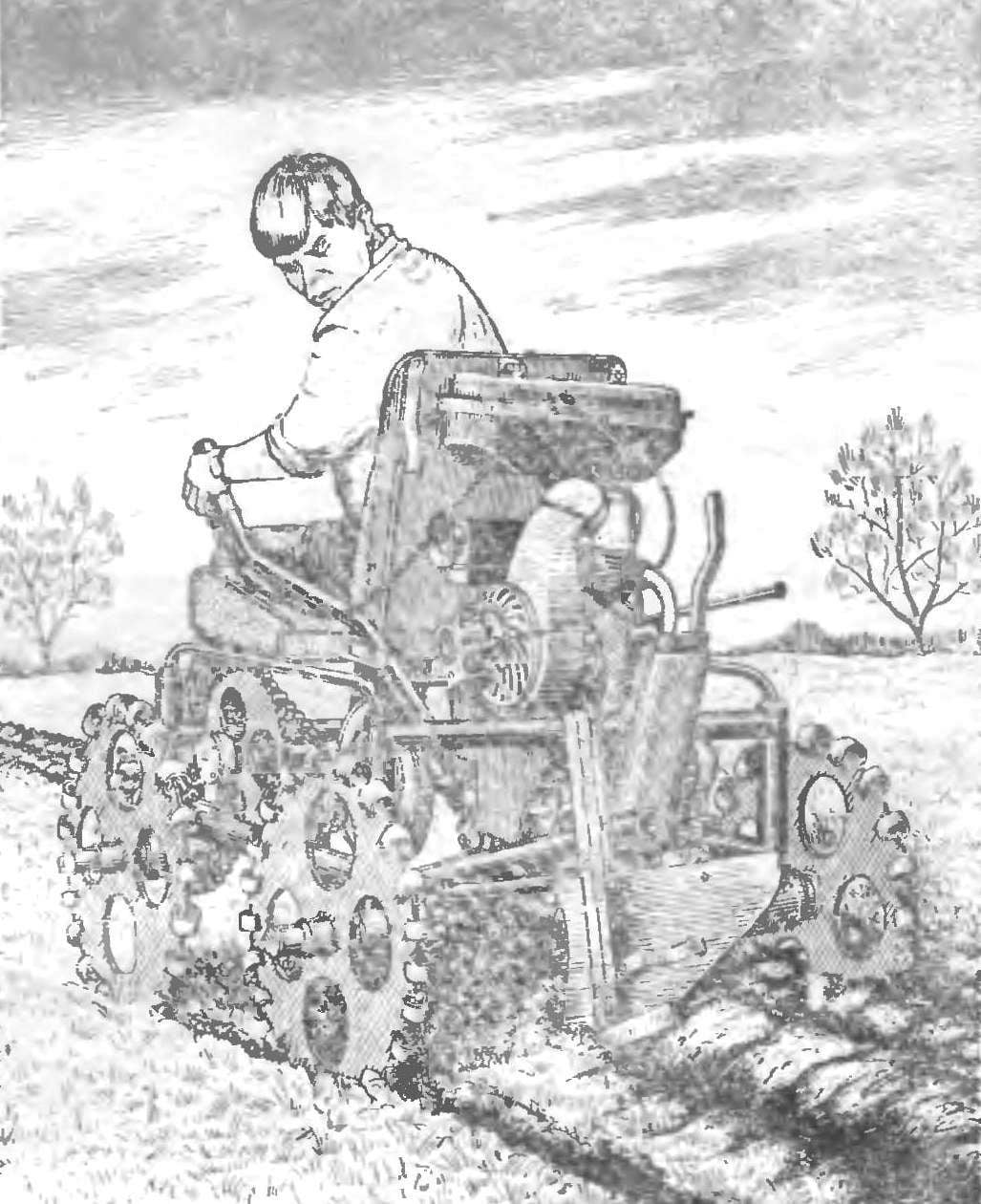
 Regular readers of our magazine are already familiar with the Kaluga Amateur designer V. N. Arkhipov, author of easy and productive tillers (see “M-K” № 6, 1982). However, Valentin Nikolaevich considers that it is not so simple as it may seem: to walk on the plowed land, driving a two-wheel tractor and trailer at the same time, is quite tedious and is not for everyone. That’s why Arkhipov undertook the construction of a mini-tractor with four wheels that “ride” him: to various agricultural work, while not on m itself. The attempt failed, and the light appeared a kind of chair on wheels — tractor “Kaluzhanin-14”. Not so long ago, the author had submitted it to the popular TV show “you can” and received the approval of the competent jury Today at the request of viewers and our readers the journal publishes drawings on which you can build the same “iron horse” helper of your household and garden plots.