One of the professions — welder — especially useful in the manufacture of frames the mini-tractor. The frame is a rectangular structure, welded mostly from channels and angles of various sections. Below it is attached almost all the transmission units to the chassis of the intermediate shaft to the rear axle. On top of the engine, controls, driver seat, wings and part of components of the hydraulic system. The front frame has the towing eye-bolt, rear — hitch for a trailer and attachments.
On “Crumbs” used ZID-4,5. Is a stationary, single-cylinder, double flap engine power 4.5 HP at 2600 rpm, which has an internal transmission with two gears (lowering and raising) and works well on gasoline A-72 And a-76. It focuses the output shaft forward in the direction of the tractor and mounted on two brackets with four screws. Therefore, the starting shaft in the back seat and close the driver that enables the engine to start, not getting up (he just jammed — turn choke carb).
Dvuhruchevoj pulley with a diameter of 150 mm the output shaft is connected by belts brand А1060 (GAZ-51) with a pulley with a diameter of 190 mm, the intermediate shaft of the transmission. Thus, the belt drive with a ratio of 15:19 allows to 2000-2100 rpm is a perfectly acceptable number of turns for the primary transmission. Belt tension is regulated by a corresponding device on the wing of the left front wheel.
Mini-tractor “Scarce”:
1 — tensioner drive belts; 2 — axis hinge of the hood; 3 belts; 4 — hood; 5 — engine, ZID-4,5; 6 — wind flap; 7 — fuel tank; 8 —a gear lever; 9 — lever manual PTO; 10—the lever; 11 — a shaft of the launcher; 12 — support of the hood (area 20×20, 2); 13 — steering column; 14 — a coupling pedal; Mini-tractor “Scarce”; 15 — throttle; 16 — floor; 17 — a front fender splash shield; 18 — hind wing; 19, 23 — jumper (area 20×20); 20 — front seat telescopic spring-loaded; 21 —the lever control of the spool device of the hydraulic system; 22 — device three-position valve; 24 — hydraulic hoses; 25 — the hydraulic tank.
Transmission:
1 — a pulley of the intermediate shaft (0190); 2 — bearing housing intermediate shaft; 3 — a flange (crankshaft GAZ-51); 4, 5 engine flywheel (without ring gear) and the clutch basket (UAZ-469); 6 — hydraulic pump NSH-50 with the gearbox power take-off (hose inlet and outlet fitting and a lever for boxes conventionally not shown); 7 — transmission (GAZ-51); 8 — drum Parking brakes (brake handle and actuator conventionally not shown); 9 — propeller shaft front fork (UAZ-469); 10 — a plug of a propeller shaft rear (GAZ-51); 11 — axle rear (from GAZ-24).
Frame mini-tractor:
1 — eyebolt tow; 2 — front hinge of the bonnet (area 40×4(1, 2); 3 — beam of fastening of an intermediate shaft of the transmission (channel 120×52); 4 — engine mounting (channel 100×46, 2 pieces); 5, 7 — traverse transaxle front and rear (area 50×50); 6 — spacer (channel 65×36, 4 items); 8 — bracket, steering gear mounting (100×100 area); 9 — floor support front (32×32 area); 10 — spar (channel 65×36); 11 — floor support rear (32×32 area); 12 — support the hydraulic tank (area 32×32, 2); 13 — CZ; 14 — mounting brackets CAT (50×50 area); 15 — strengthening bracket (strip 25×5); 16 — bumper (32×32 area); 17 — bracket I-beam front axle (area 45×45, 2); 18 — floor support side (area 32×32, 2); 19 — crossbar (channel 65×36); 20 — a lining reinforcement (steel, sheet s5); 21 — Bush power.
Front axle:
1 — wheel (from mechanical rake, 2); 2 — lever swivel (from the “Moskvich-412”); 3 — rib (steel, sheet s5. 2); 4 — bracket (channel 65×36); 5 — axle turning (GAZ-24, 2 pieces); 6 — bracket suspended (cardan shaft UAZ-469); 7 — washer (brass 2); 8 — a bolt with thread M14; 9 — bushing suspension bridge; 10 — beam axle (from the rear axle of the electric truck); 11 — retaining bolt (2 PCs); 12 — plate reinforcement (steel sheet s10, 2); 13 — transverse traction (shortened longitudinal thrust from the UAZ-469); 14 — lever steering linkage (2 PCs, front view conventionally not shown); 15 — insert hex turn-key 19.
Belt tensioner:
1 —screw-gate M16 2 — M16 locknut; 3 — housing (area 28x28x3); 4 — slide (area 25x25x3); 5 — pin (M12); 6 — M12 roller axis; 7 — the axis of the roller; 8 —roller dvuhruchevoj.
Hydraulic tank:
1 — prop (area 25×25, 2); 2 — bottom (steel, sheet s6, 2); 3 — the tank body (tube 100×5); 4 — fitting the exhaust (pipe 20×3); 5 — inlet; 6 — the case of the siphon; 7 — siphon; 8 — end cap.
The intermediate beam of the front axle:
1 — bracket (area 45x45x5,2); 2 -beam (channel 100x46x7).
Mountable device:
1 — lag (area 50×50, 2); 2 — box “square” (], 2); 3 — step ladder (2); 4 — “square” (rod 28×28); 5 — Bush remote bottom (tube 48×4, 2); 6 — cylinder power (from agricultural equipment); 7 — bracket cylinder (area 50×50, 2); 8 — bushing remote top (tube 30×2,5, 2); 9—frame of the tractor; 10 — the crossbar of the cylinder (rod Ø20); 11 — nut М20х 1,5 (2); 12 — bushing power (tube 40×3, 2 PCs.); 13 — shot cylinder rod (rod Ø24.); 14 — nut М24х 1,5 (2); 15 — M16 nut (4 PCs.).
The attachment of the floor and rear wing:
1 the jumper front (area 20×20); 2 — stiffener (area 20×20); 3 — wing; 4 — bracket wing (32×32 area); 5 — floors (steel, sheet B5); 6 — floor support side (32×32 area); 7 — spar (channel 65×36).
Muffler:
1 — flange-inlet (short tap coupler); 2,4,6 — link exhaust pipe (pipe 32×3); 3,5 — squares 7 —resonator (jointed pipe from GAZ-24); 8 — bottom (steel, sheet s4, 2); 9 — pipe exhaust; 10 — pin (rod Ø5).
The intermediate shaft 32 mm diameter rotates in two ball bearings mounted in the cylindrical housing, which is drawn with four bolts to the beam frame at the bottom. Design, in General, simple, so in particular–explanation does not need.
To the rear end of the intermediate shaft is welded to a flange cut from a crankshaft of the engine GAZ-51. To the flange with four bolts M 12×1,25 are attached to the engine flywheel (without ring gear) and the clutch basket UAZ-469. Lever clutch rendered in the space between the basket and the gearbox and is located on the left mounting bracket transaxle (this bracket has a gain — podvarennoe to it a steel plate, which is inserted the axle of the swing arm bolt M10). Rod with ears on the ends of the lever connected to the clutch pedal, located under the left foot of the driver.
Transmission from GAZ-51 with four forward gears and one back. For mounting box has six holes in the rear beam and vertical bracket of the frame. The gear lever and hand brake handle removed between traverses to the top.
Homemade propeller shaft made from the same shafts of the UAZ-469 and GAZ-24, gearbox connected with rear axle (from the car “Volga” GAZ-24) mini-tractor. (It should be noted that because of the offset pinion gear of the rear axle, the longitudinal axis of the transmission located 20 mm to the left of the longitudinal axis of symmetry of the frame.)
Because the track of the wheels of the “Volga” is broader, covers the axle shafts and the driveshaft shortened. The technology alteration was used. Housings were cut closer to the flanges of the wheels and brought to the desired length; the site of the incision is centered on a lathe and there, in the loom, first tack-welded by welding at three points, and then at low speed the spindle is welded around the circle and left in a clamped condition until cool.
Similarly converted and axles. Just before the three-point tack they were connected by with studs M16 screwed in axial threaded holes drilled in the ends centered. They also cooled down on a lathe. It should be added that hub from the axle — “vazovskie” because the rear wheels “Crumbs” — also from the UAZ-469 (size 8,40—15″).
To the bottom flange of the side members of the frame the rear axle is attached to its support cushions with four screws. Earrings, welded to the axle housings below the mounting pads were moved closer to the symmetry axis of the mini-tractor to attach it to the hitch.
Such transmission provides the mini-tractor working speeds in the range of from 5 to 20 km/h.
The design of the front axle is also used components and parts other machines. Wheel size 5.0—10”, for example, from agricultural machinery (mechanical rake). And as the basis used beam rear (steering) axle of the electric truck. To it is welded thick-walled bushing suspension and two plates (to strengthen).
To the hub through a pivot and thick brass washers attached hanging bracket (plug from the propeller shaft UAZ-469), which four bolts fastened to the intermediate beam front axle, which will be discussed later.
Swivel pin taken from GAZ-24. From below them screwed in slightly modified levers of a steering trapeze from the “Moskvich-407”, and on top — just to the right axle! — welded swivel bracket. It is made of steel channel with curved upper part, devoid of shelves. To it is attached by welding a shortened swing arm from the “Moskvich-412”, connected by a thrust with a plow steering mechanism. The latter, also from the “Moskvich-412”, mounted on the frame on the right hand side and is attached with three bolts to a special mounting bracket. Steering column a little shorter.
As the cross rod of a steering trapeze the longitudinal thrust is taken from the UAZ-469. She’s cropped and fitted with an insert of hex rod under the key 19 mm for easy adjustment of the camber of the wheels.
To frame the mini-tractor attached front axle by means of intermediate beams, made of steel channel and two corners. The advantages of this method of mounting is that if you need to disconnect the bridge for repair, it is not necessary to crawl under the tractor and Unscrew the hanging bracket.
It is enough just to bend down and Unscrew the four bolts on the intermediate beam, and then get on with the bumper and to shift the “Baby” in the side of the bridge will be in your hand!
The engine hood is welded from three steel sheets with thickness of 1.2 mm and mesh venting (it front). Before welding the edges of the leaves were beaded.
Of the same metal made front and rear fenders.
Taken for floor steel sheet thicker — 5 mm and attached with screws sa-moresome to three transverse and four longitudinal supports from the corner 32×32 mm, welded to the frame rails.
On the floor (above the rear legs) are installed in the driver’s seat, equipped with a telescopic spring-loaded stand. The seat frame is made of pipes with a diameter of 20 mm. Cushion is made of plywood, foam and leatherette. Strut consists of two tubes: the top (diameter 40 mm) and lower (diameter 50 mm). The first is welded to the seat frame, the second to the floor. They put the two twisted together spring from the front suspension of the “Moskvich-2141”, balancing the weight of the driver.
To work with removable salhotra-diami mini-tractor has a hydraulic system and hitch.
The hydraulic system includes PTO (located on transmission right), pump NSH-50 (ibid), tank (on special supports in the rear of the frame), three-position slide valve device (on the left bracket and the power cylinder), the force cylinder and hoses.
Hitch consists of two lag — tubes of rectangular cross section, welded from the corner 50×50 mm. the Front ends of the lag engages with the earrings under the rear axle, and back through the “square” connected to removable equipment. About halfway to the joists is attached to the crossbar for stock power cylinder. All connections are hinged device deliberately performed with gaps. This is done in order to design does not jam, even when significant distortions and fluctuations, which are inevitable during operation of the plow, harrow, cultivator or Hiller.
Of course, in the Arsenal of tractors there and a cargo truck. What is the harvest? Truck hooking it to the towbar using a crossmember on the frame and holds the body of three hundred pounds of potatoes. Traction as possible “Crumbs” such that it can transport loads up to tons.
A. TIMCHENKO
Recommend to read ROCKET FROM THE SPORTING PAST a Spectacular high-speed radio-controlled model-polyopia missile boats based on the hull of the sports racing model, has been one of the trends of creation of ships with dynamic... CHILDREN’S TWO FLOORS For 10 years I read the magazine "modelist-Konstruktor", and from year to year it is more and more like me. However, all this time was your "dependent": only used published drawings for... 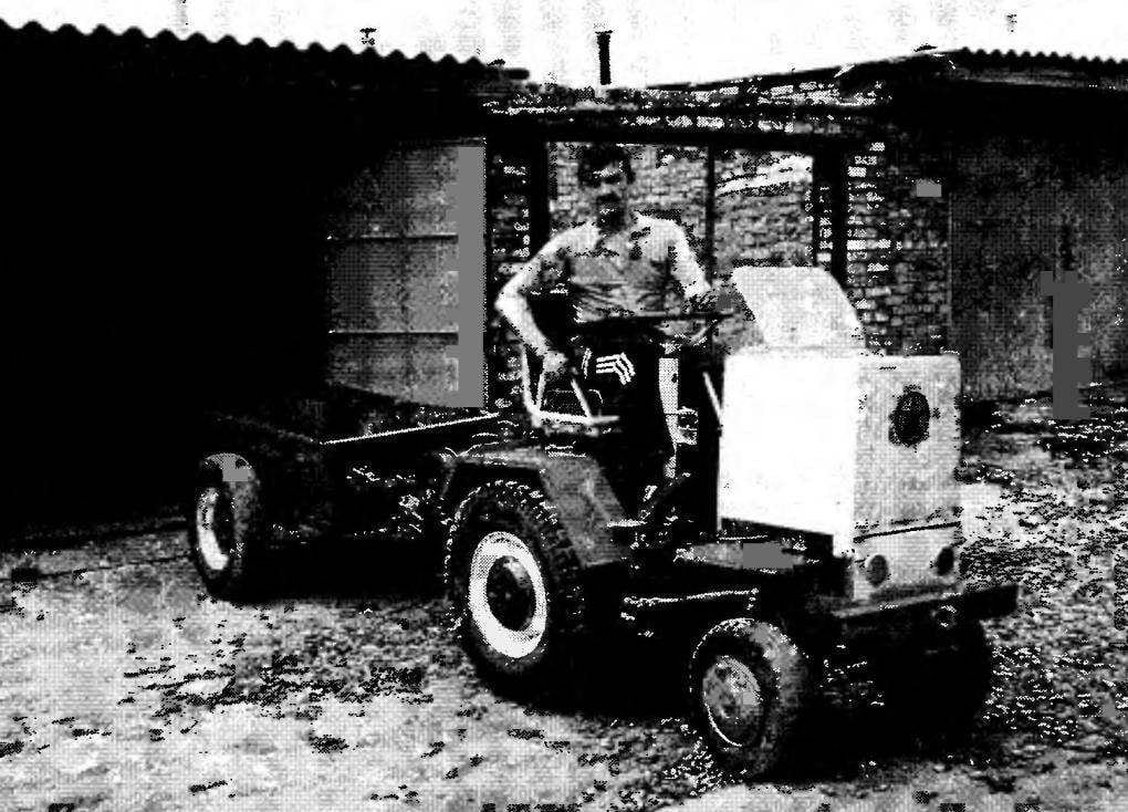
 This mini-tractor, Y. V. BALABIN, Amateur designer from Moscow city Lotoshino, built from what was found in a garage at home, with friends, in a scrap yard. However, “Scarce” (as he called his mini-tractor) is in the extensive garage of craftsman privileged position. Despite the fact that next to him are still jeep “Hugo” mini-mobile “Colibri”, the mechanical horse and maintenance — first and foremost, and repair in the shortest possible time. But how else? “Baby” is in fact the breadwinner of the family of its Creator! Without him and the garden for planting potatoes treated, and the crop will not be harvested.