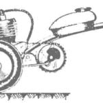
Almost all the details of the motor-plow homemade, but they are not too complicated, and make them can anyone who has plumbing skills.
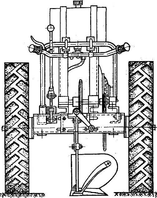
The basis of the motor-plow — frame, welded from a steel profile “area” 50X50X5 mm. it includes an engine, drive axle, plow and controls.
The wheels are homemade. Each consists of a Central hub, twelve spokes of steel rod Ø 14 mm, rim (steel strip with a thickness of 6 and a width of 120 mm) and rubber-cord protector with a large picture cut from old tyres.
A Central hub of the wheel is equipped with an overrunning clutch is much easier than differential, and more reliable than one drive wheel. The wheel Assembly is. Are screwed in the hub of the spokes on each’re in for a nut. Then the spokes are sequentially passed through the holes in the steel strip and each of the rim from the outside, lock the second nut. After balancing and alignment rim sealed or sealed inside the panel and screws. For fixing the tires on it are two area; each with two holes, through which skipped the pinch bolts M10.
Drive axle machined out of rod Ø 40 mm (Steel 40). To make it better in the centers, paying attention to the Seating surface, the purity of their processing should not be below the seventh grade, and accuracy class not less than the second. Everything said should also be referred to the intermediate shaft.
On the motor-plow uses a two-stage chain gear. The gear ratio of the first stage of deceleration is 3,65, the second — 3. These figures must be strictly adhered to: the speed of the motor-plow at such a reduction ratio of about 4 km/h.
All sprockets chain gear — homemade. As with the intermediate, and the drive shaft connected on the dowels.
Fig. 1. Motor-Plow V. Petroni:
1 — shield 2 — slide, 3 — blade, 4 — bracket 5 — screw, 6 — shift lever, 7 — button stop engine, 8 — intermediate shaft, 9 — the mechanism of chain tension, 10 — vostokfilm engine, 11 — magneto engine, 12 — muffler, 13 — contgroup, 14 — the wheel 15 — the axis of the wheels of the motor-plow, 16 — crank start engine, 17 — sprocket (Z=45, t = 39,05 mm), 18 — sprocket (Z=15, t=19,05 mm), 19 — sprocket (Z = 62, t=12.7 mm).
Fig. 2. Chassis of motor-plow:
1 — proektirovaniya tire wheel, 2 — wheel, 3 — frame, 4 — overrunning clutch, 5 — axis, 6 — bearing No. 1506, 7 — bearing, 8 — sprocket (Z = 45), 9 — coupling, 10 — cover 11 — washer 12 — clip 13 — spring.
Fig. 3. Plow parts:
A — shield B — the blade (scan), In — lever, G — slide.
Particular attention in the manufacture of metaphora should be given proper plow. Inaccuracy in the “geometry” can undo all your hard work, because the plow so the plow will not. The main thing — correctly to set the blade, i.e. the part that turns the soil over. The optimum angle of 50°: with a smaller resistance of soil increases dramatically, which will cause slippage and vibration of the whole Assembly.
On the frame of the plow is placed so that it was possible to change the depth of plowing and the installation angle. For this is the arm, the rotation of which the plow pivots on the lever, raising or lowering a sock. To adjust its position and on the move.
The plow is attached to channel No. 10 to the rear of the frame. The width can be changed, for which the channel is slotted, through which the working body is fixed with bolts M12.
The engine of the motor-plow — scooter T-200. Its layout is very complex. The controls are all grouped on the arm.
In addition to the primary purpose, the motor-plow can also be operated in conjunction with a single axle trailer, using transportation of various cargoes.
V. PETRUNYA
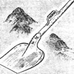
 Isn’t that a stark contrast: while the fields of collective and state farms are treated today powerful “Kirov workers”, the private plots of rural workers in the old plow at best plow horse, and at worst — just dig with a shovel. This work is unproductive, time-consuming, moreover, requires considerable physical effort. That’s why many of the “homebrew” without waiting for the industry mastered the production of agricultural micro-technology, develop and produce motology and microfracture, cultivators and power hoes. In today’s publishing, you will be able to meet with the drawings and description of a homemade motor-plow, constructed a work of pumping plant VI Petruna from the village Svessa, Yampolsky district, Sumy region. Design although it did not meet all the requirements of modern design, completely reliable and fully justifies the name of metaphora.


