The car was small and lightweight (weight approximately 200 kg), unpretentious in operation and economical and very durable and powerful. Easily carries a cart with a load in a ton or tank to 800 liters of water. Great job with plowing the garden, on the rear drive wheels to put on lugs.
What predstavljaet “mini-Hercules”?
This is a four-wheeled car with a motorcycle roller 12-horsepower engine T-200, equipped with a carburetor K-28G, oil air filter, magneto, fire pumps, generator from GAS-5 DIGITS and an additional three-stage gearbox (KP) from GAZ-69, providing, together with the KP of the engine 12 speeds forward and four back. Suspension bridges rigid (without shocks and springs), dependent.
Kinematic scheme of transmission:
1 — shift lever; 2 — engine; 3 — coupler spline; 4 — bearings 204; 5 brake pedal; 6 — sprocket (z = 12, t = of 15.55 mm); 7 — primary shaft; 8 — chain tensioner; 9 — transmission, additional (GAZ-69); 10 — sprocket (z = 25); 11 — bearing 205; 12 — drum brake (from motor scooter “Tula-Tourist”); 13 — bearings 11206; 14 — rear wheel; 15,18 — bearings 210; 16 — differential (UAZ-469);17 — sprocket (z = 24); 19 — sprocket (z = 12); 20 — intermediate shaft; 21 — the star (z = 20); 22 — sprocket (z = 13); 23 — lever for extra gear.
General view of the tractor:
1 — body; 2 — tank; 3 — seat; 4 — a casing of the generator and magneto; 5 — the lever of a gear change; 6 — front front panel (STZ, angle 25x25x3, 2); 7 — electroceramica; 8 — the steering mechanism (motorized FDD); 9 — front wheel (scooter “Tula-Tourist”); 10 — engine T-200; 11 — compartment powertrain; 12 — rear wheel (sidecar FDD).
Power frame (all components made of Vs):
1 — side member, front (corner 50x50x5); 2,20 — elements of the frame are polycarbonate (25x25x3); 3 — front spar (corner 50x50x5); 4 — bracket engine mounts, front; 5— front of engine compartment, front (area 40x40x4, 2); 6 — elements of the frame of the engine compartment, the upper (area 25x25x3); 7,41 — stand bearing units shaft of the transmission (area 40x40x4); 8 — front of engine compartment, rear (area 25x25x3, 2); 9,14,25 — frame elements of the transmission compartment (area 25x25x3); 10,13 — crossmember rear (area 70x70x7); 11 — front rear (corner 50x50x5); 12 spacer under the bearings of the intermediate shaft; 15 — longitudinal beam (pipe, 40x40x5,2); 16 — amplifier (corner 50x50x5, 2 PCs.); 17,32,33 — crossmember front (corner 50x50x5); 18 — longitudinal struts (area 50x50x5); 19 — hinge lugs of the front axle (area 70x70x7); 21 — spars engine mounts (area 32x32x4); 22 — cross member mounting racks (area 32x32x4); 23 — transmission, additional; 24 — cosina (area 40x40x4); 26 beam fixing hook (50x50x5); 27 — bracket hitch plate (70×7); 28 — Board trailer (steel channel welded from the corner 70x70x7); 29 — brace (plate 25×3, 2); 30 — amp boards (plate 70х7);31 ososki(болгМ18,hot,2pcs.); 34 — bolt M10 (8 PCs); 35 — front engine mounts, rear (area 32x32x4); 36 — cross-medium (area 32x32x4); 37 — thrust engine mounts, rear; 38 engine; 39 — the mounts of the CP (area 32x32x4, 4 pieces); 40 — node input shaft, bearing; 42 — brace center support (area 25x25x3, 2); 43 — a amplifier hook (plate B7); 44 — hook of fixing the plow in the raised position plate (s7); 45 — hook bracket, welded (area 40x40x4); 46 — eye attachment of the plow plate (45×5); 47 — site of attachment of the steering mechanism (50x50x5 area, stub, 2); 48 — brace Polycom (25x25x3, 2); 49 — jumper (area 50x50x5).
Rear axle:
1 — the cross-beams of the power frame, rear; 2 — beams of the power frame, longitudinal; 3 — axis; 4 — platform (steel 7, the plate s7); 5 — differential; 6 — a star (z = 24); 7, 8 — nodes bearing; 9 — the “key” (screw M10); 10 — wheel hub.
The basis of the tractor is a frame structure made of steel pipes of rectangular section and different parts. Connections of all structural elements are pre-bolted and then welded. Raised and reinforced front struts spars with Polikom of the driver’s seat to form the gap of the front of the bridge. Welded to the side members stand with their struts. The average volume of the frame is occupied by the engine and its components, and in the rear placed additional gearbox and transmission units.
Frame sheathed with 2 mm sheet metal, and Bocaina the engine compartment and the top panel of the compartment of the transmission is removable. Front and rear fenders are made of the same sheet, reinforced steel area, and attached to the frame with bolts.
The lattice structure of the body turned light and easy to operate. If necessary, the body is easily dismantled by one person in a few minutes.
The engine is mounted on special rails by means of regular connecting nodes and the bottom node is directly connected to the side members, the front with arched adapter, and rear — using thrust running on the spar racks. In addition, the latest enhanced traction, drawn by the bolts to an additional transmission. The box is held firmly to the four corner posts placed in the middle and oblique crossbars.
The output shaft of the engine is modified: instead of the drive sprocket to its free end is welded to the splined bushing for connection with the input shaft of the transmission.
The transfer of torque from the engine to the drive wheels is a transmission consisting of three chains, paradnogo shaft with the sprocket (z = 12), additional KP. intermediate AAL with two asterisks (z = 12 and z = 20) and the brake drum and axle shafts of wheels connected by a differential. On left axle shaft mounted driven sprocket (z = 24). Sprockets, shafts, axles and bearing assemblies in which they rotate, are chosen from the standard used in agricultural units. The tension of the first circuit is provided by the position of the sprocket of the tensioner, and the other two — due to the selection of shims under the supports of the intermediate shaft and its displacement along the power frame. Almost the same happened so that this complex operation had to spend only once during Assembly of the tractor and further to her not to return.
Bearings of the axles of the drive wheels mounted on six special platforms made from strips of raw spring steel and rigidly secured to a powerful rear cross. Wheel firmly planted on the axis and, as shown, is fixed against rotation and axial displacement of the three “keys” (screws) every.
The front axle of the tractor is a swinging tubular beam-balancer connected by a pivot shaft lugs of the front spar of the power frame. With both ends welded to the rocker chiseled fists with planting belts to install the rotary with the axles welded to the axle shafts of the wheels. On top of the axle is wearing, and then fixed by dowels and nuts steering arms, articulated to the steering rod. All the joints made the type of bearing friction with the packing them in grease grease.
Moving the tie rod is located in front of her steering of the sidecar FDD with a slightly shorter rake. To install it on the machine to the front side members is attached below the welded parts of the site.
The composition of the tie rod consists of two slide bolts adjust toe.
Good reliable truck needs a tow hitch. So the constructor did. In addition, it is universal — clings to any cart or plough. The unit includes trailer Board, welded from two parts, a hook rigidly secured to the upper rear crossmember. The latter serves to retain the plow in the raised position. In the Board drilled a series of holes designed to install pin and stretch marks of the plough.
Front axle;
1 —wheel hub 2 – slide tie rod (area 40x40x4, L260); 3 — beam balance (STZ, tube 40x40x4); 4 — eye of the power frame; side member 5 of the power frame, front; 6 — fist (STZ); 7 — axle swivel (45 steel); 8 — bearing 180206; 9 — the bearing 180205; 10 — grease fitting; 11 — tilt axis (bolt M20x1,5); 12,15—washer (bronze, s2); 13 — bushing (steel 20); 14 — cheek(STZ, plate s7, 2); 16 — bushing bipod (STZ); 17 — fry (STZ, plate 200x40x10); 18 — nut М24х1,5; 19 — finger bipod (steel 45); 20 — shelf slide (STZ, plate 100x40x5); 21 — bushing tie rod (STZ).
The driver:
1 — seat, 2 gear shift lever; 3 — the clutch pedal; 4 — wheel steering; 5 — bracket fastening the front panel; 6 — electrochrome (2); 7 — panel front (STZ, lisg s); 8 — the gas pedal; 9 — the brake pedal; 10 — struts (area 25x25x3).
Grouser:
1 — loops of a wheel; 2 — rim; 3 edge; 4 brackets coupling; 5 — rivet, 6 — bolt coupling (2 PCs.)
The plough (all parts except the blade, made of Vs):
1 — Board trailer; 2 — Ø12 pin; 3 — cover plate (plate 170x50x10); 4 — beam (pipe 60x30x5); 5 — stretching (chain); 6 — M10; 7 — chain tensioner (M10); 8 — loops (channel 60x50x7); 9 — front wheel (corner 50x50x5, L400); 10 — wheel of the field; 11—blade; 12 — Board of the field; 13 — front plow (pipe 60x30x5); 14 — an arm of the main thrust (листѕ6); 15 — clutch screw; 16,24 parts bracket stand field wheels (corner 50x50x5); 17 — plate (plate 140x40x5); 18 — thrust main (pipe 33,5×6); 19 — thrust lifting of the plow (pipe 21,3×3); 20 — hook the power frame; 21—the lever lift plow (pipe 33,5×5); 22 — arm (tube 23,5×2,5); 23 — tilt axis stands plow (bolt M18); 25 — pull bracket hoist (area 30x30x3); 26 — bracket chain tensioner (area 50x50x5, 2); 27 — lug (sheet s5); 28 — amplifiers (sheet s5); 29 bolts M14.
Tie rod:
1 — tie rod bushing; 2 — shelf slide; 3 — bracket slide (STZ, plate 40x40x4); 4 — bolts M8; 5 — pull the brackets (STZ, plate 200x30x5); 6 — beam (area 40x40x4); 7 — eye of the finger, Rei-Ki of the steering mechanism (STZ, plate 100x50x7); 8 — slides; 9 — a bolt of adjustment of a convergence of wheels.
With the installation of the machine mounted plow, it turns from a tractor wheel tractor.
The plow design E. Kulikova consists of beam, plow blade and wheel on the adjustable racks; has a mechanism to adjust the depth of plowing and by the angle of the plow blade, lift arm of the plow and banners, preventing the buildup of the whole Assembly in the horizontal plane.
The beam is a steel pipe of rectangular cross section, equipped with brackets for attachment of lifting of the plow and chain tensioners, strap lever hoist and straps. The last stand hold the plow in a vertical longitudinal plane. To facilitate access to the bolt connections on the top shelf of the channels of the straps, half-cut. To the left of them welded to the stand bracket wheel.
The design of the cleats is very simple: a steel strip with a width of 90 mm, riveted wheel covers, edges, and tensioning bracket. To wear on wheels, no need to pull the tires, and enough poddomkratit rear axle, throw the lugs and the pre-pull of their long technological pins. Then put the regular bolts and remove the studs.
About the masters of high class say — “Golden hands”. The same can be said about Eugene Anatolyevich. They are actuated tractor operated year-round for over seven years and have never been repaired.
Recommend to read FOUR PROFESSIONS ONE MODULE Adherents of certain types of modellers rarely use the design solutions and technological methods inherent in other areas of technical creativity. And it is in vain. The proof is a... TANK, WHOSE “SWINGING” TOWER Oscillating turret French light tank AMX-13 was only one of the features of this machine. Another feature is a violation of the creators of the familiar classic layout, when the power... 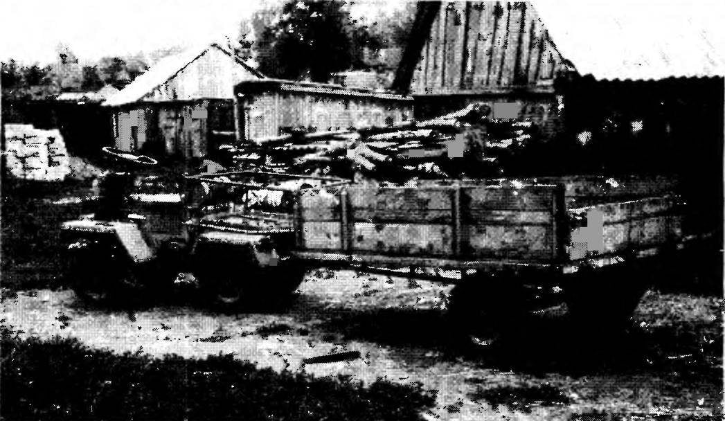
 Many years spend their holidays together with the family and the village is Big Yak-Shen Nizhny Novgorod region. Lovely place, kind and friendly people, feasible physical labor on a small kitchen garden that still need a citizen to stay? Working in the magazine and receiving letters from Amateur designers from different regions of Russia, thought: why not get e-mails from places that have become to me already native? Really there moved their Kulibin? Became interested, to make inquiries and last summer’s arrival was pleasantly pleased.