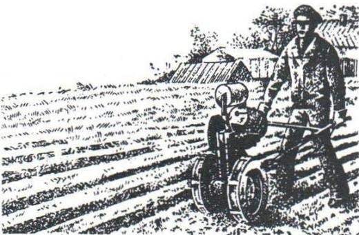
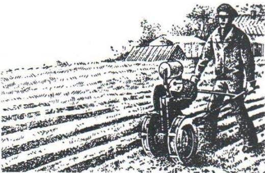
Since then, residents of suburban villages Moroski often seen as working on the plot mechanic assistant gardener. Have zakonchilsa potatoes – Ilichev, replacing wheels and tilling on, led him to the garden to till landing… you Need to transport anything, and now instead of the plow or Hiller behind “Vyatichi” the self-made truck. Humming engine, tillers confidently pulled up to the top, loaded the cart and rider into the bargain – almost half a ton.
Fig. 1. General view of the cultivator:
1 – frame; 2 – way chain; 3 – a leading chain; a 4 – unit intermediate sprocket; 5 – intermediate bridge; 6 – engine; 7 – fuel tank 8 – valve fuel tank; 9 – carb; 10 – engine; 11 – a bolt of fastening of the engine; 12 gearshift lever; 13 – output sprocket; 14 – an arm; 15 – the bolts of the suspension holder, 16 – clip holder; 17 – the plow; 18 – steel control knobs; 19 – control cables (suspended torn); 20 – supporting wheel; 21 – drive sprocket; 22 – the case of the suspension bridge; 23 – clutch lever; 24 – a left control handle; 25 – right arm; 26 – the lever of the gas; 27 – kick pedal; 28 – lugs; 29 – main wheel; 30 – flange of the main wheel
Fig. 2. Frame:
1 – loop pendants holder; 2 – foot; 3 – the Central focus; 4 – upper beam; 5 – a platform of the navigation bridge; 6 – platform intermediate axle; 7 – inclined beam; 8 – a lateral stop (2); 9 – adjusting bolt (3 PCs); 10 – the lower beam; 11 – earring
Fig. 3. The scheme of refinement of the engine:
1 -troopered carburetor; 2 – the lever of kick starter; 3 – a gear lever
Fig. 4. Bracket:
1 – base; 2 – rib; 3 – support; 4 – front lip of the clamp; 5 – rear lip; 6 – tightening the bolt (2 PCs); 7 – clamp; 8 – bearing; 9 console; 10 – thrust nut; 11 – the terminator
Fig. 5. Plow:
1 – Coulter; 2 – reflector; 3 – emphasis
It was time to prepare for the winter firewood and then Ilichevo helped his microuniverses. He removed the engine from the frame of “Vyatich” along with a mounting bracket and put on a simple device with a pendulum circular saw.
The obvious benefit of walking tractor in agriculture.
Conventionally, this cultivator can be divided into five parts: frame, engine group, transmission, wheel, and holder of tillers with controls. So, in order, and consider the device “Vyatichi” (Fig. 1).
Frame (Fig. 2) is welded from three steel I-beams -segments channel number 8. In the wall of the upper beam in two holes tapped M8 for mounting the bracket to the engine. There, just below the holes, welded the Central focus – the area with the adjusting bolt М8х60 mm that can move the bracket on the frame. Why – will become clear later.
To the bottom and the sloping beams of the frame is welded by square steel plate platform chassis and the intermediate bridges of the tillers. The holes in the chassis platform of the bridge for fastening of the housing is cylindrical. In the platform, the intermediate they are made in the form of grooves, and below the platform to the shelves of the inclined beams welded to two lateral focusing with adjusting bolts М8х60 mm.
To the rear of the frame is welded rectangular plate – heel, and to her-outside – loop suspension holder. The inner side of the heel of the welded stud with a hole 10 mm in diameter, which includes the adjusting bolt holder.
Motor group “Vyatichi” consists of motor, bracket attaching it to the frame, the output sprocket and fuel tank. The engine is taken from the well-known motor scooter “Vyatka-150M” (and from “Electron”), Serious modifications of it have not been, but something in him changed. Pipe of the carburettor (Fig. 3) is separated from the flange, turned 180° in the horizontal plane and re-welded to the flange (otherwise the installation of the engine in the frame the carb will run into the design; for the same reason, and removed the silencer). Lever kickstarter in two places notched, bent at the notches and welded. After that, the lever, dropping down when the engine is started, stopped to touch the wheel.
Finalized and the sector gear selector. To it is welded a steel rod with a ball on the end, which you can easily reach behind the control knobs by Megna.
Output sprocket (Fig. 1) put on the PTO shaft of the engine. She has 19 teeth with a pitch of 12,7 mm sprocket Splines and the shaft is appropriate.
The engine is mounted on the frame with a bracket welded from several parts, mainly from segments channel number 8 (Fig. 4). Clamp bracket, tightened the bolts, clasps the neck of the output shaft and securely holds the motor. The bracket attached to the frame with two bolts For this М8х10 mm. at its base propylene grooves, which allows to move the bracket on the frame and thereby change the tension of the drive chain (adjustment screw when it rotates in the stop nut welded to the bottom of the console). And below the bracket when the adjustment is not misaligned, the edges of its base welded to the limiters which Orient the bracket along the top of the beam.
The fuel tank of cylindrical shape is mounted on two struts above the engine. The fuel it is supplied to the carburetor by gravity.
The transmission is an intermediate and driving axles (Fig. 1), taken from decommissioned potato harvesters, sprockets, flanges, wheels and chain. The interim bridge is placed on the platform of the inclined beams of the frame and may be slightly moved in its grooves, pulling the running gear chain. Tension is adjusted with adjustment screws М8х60 mm in the lateral struts of the frame.
On the left are the shaft splines the axle is mounted and fixed by screw М6х8 mm block of intermediate stars. Big one has 64 teeth, the smaller 18. Step of teeth equal to 12.7 mm. Torque to the output sprocket of the motor circuits of the motorcycle “Java” is transmitted to the intermediate axle and the chassis. There sprocket has 30 teeth with a pitch of 12.7 mm and is made with the flange left wheel walking tractor. Impaled it on the splines of the left axle shaft end and screw fixed М6х8 mm. To the splines of the right end of the navigation bridge similarly installed and secured to the mounting flange of the right wheel.
The wheels on the “Vyatich” motorolleri (Fig. 6). Only drives their attachment to the flanges of a homemade, cut from steel sheet. For a better grip with the ground wheels equipped with grousers – corners with shelves 25 mm wide (eight pieces in the wheel). Corners – two types: half of them with legs, a half without legs. They are fixed, alternating, to combine the two chains put on the tires. That chain didn’t come off, the legs off of the cleats are bent to the wheels.
When plowing motorolleri left wheel is removed and in its place put support. It is entirely metal (Fig. 1): a disk cut from sheet steel, and eight lug from area with shelves, width 25 mm. Connect the corners with the disc by welding. Support the wheel to the flange is fastened by the same bolts that motorolleri.
Finally, the last node is the holder of tillers with controls. Hanging it on hinges at the rear of the frame. The node represents a welded construction (Fig. 7), the basic details which sections of pipe and channel number 8. The holder is made directly from channels: one, to the shelves which is welded to end wall made clip (it is attached tillage operation), one adjustable bracket. The lower two holes of this bracket is made in the form of grooves. If the bolts in them to release, and adjusting the mounting bolt nuts to move relative to the earring frame, the mounting angle in the vertical plane of, say, a plow will be within 8°. Optimal installation angle of the plow for each soil type is determined, as a rule, during operation.
The heel holder is welded handles. The connection was reliable, the weld is reinforced slip the gusset plate and the stiffener. At the ends of the pipes wearing plastic or rubber handle. In front of them screws М5х8 mm fixed clamps levers of the cultivator: left clutch lever, right gas. The wires from them go directly to the clutch and the throttle of the carburetor of the engine. All these controls of the scooter.
Fig. 6. Main wheel:
1,5 – lugs; 2 – wheel; 3 – wheel; 4 – disc; 6 – chain
Fig. 7. Holder with knobs:
1 – crossbar; 2 – handle; 3 – gusset; 4 the rib; 5 – foot; 6 – wall of the holder; 7 – bracket; 8 – plug; 9 – adjusting screw; 10 – the axis of the bolt; 11 – yoke holder
In conclusion, a few words on tilling tools. Chisel and cultivator-Hiller is taken without alterations from decommissioned cultivator. They well destroy the Packed earthen crust and Spud potatoes. But the plow – improvised (Fig. 5). The basis of it – Coulter normal mounted plough. Bottom welded on it, the focus of pointed steel plate, and the top – blade – reflector. Additional elements help to shape the furrow. To strengthen this instrument in the clip holder in the front Coulter drilled two holes. Using them, you can change the depth of plowing.
Recommend to read BATH WITH A SAMOVAR Bath anciently considered one of the most effective "preventative care" for the human body. Since time immemorial are popular and are being built in some places even today the simplest... THE STOCK DOES NOT PULL HIS POCKET Paradoxically, but in the early 60-ies of the last century escort fleet the largest sea powers of the world — the United States of America — was in very poor condition. It is based on...