Fruits are dried in different ways. Most often — by the air-solar method, which, besides obvious advantages (simplicity, availability, etc.), has well-known drawbacks.
The proposed solar dryer design is free of many disadvantages inherent in other constructions. The “greenhouse effect” works in it, as they say, at full capacity, providing a temperature under the film 20—25°C higher than the ambient temperature.
The drying process here proceeds almost 3 times more intensively: due to the inclination of the drying platform and the temperature difference of the air, conditions are created for optimal circulation of the latter inside the unit and for the positive effect of natural convection. Part of the solar energy is accumulated in the soil (under the “bottom” of the dryer, which is blackened roll paper spread out), allowing the daytime drying cycle to be extended by 5—6 hours. The unit’s output, despite its seemingly “modest capacity,” is 0.3—0.5 kg of dried fruit per day per square meter of radiant surface.
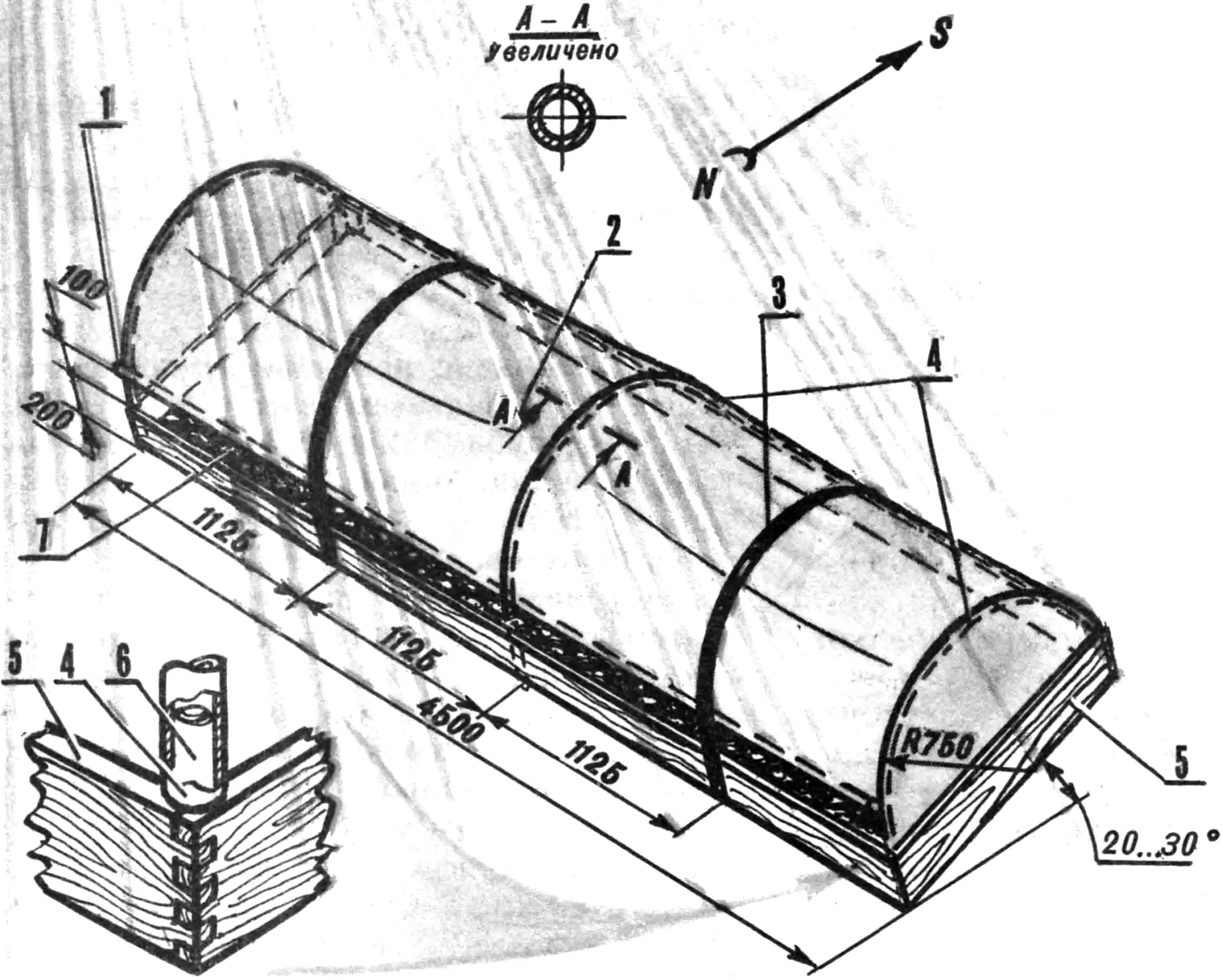
1 — crossbar (aluminum tube filled with sand), 2 — transparent cover (polyethylene film), 3 — tension device (elastic bandage), 4 — frame arches (aluminum tubes), 5 — frame (board 20X200 mm), 6 — arch mounting post (steel rod), 7 — heat-absorbing base covering of the dryer (dense black paper).
At first glance, the solar dryer design differs little from traditional “film” greenhouses. Essentially, it is the same box with an arched roof of transparent synthetic material on a rigid frame. Any material can be used for the sides. For example, boards of suitable dimensions. Joined together with tenons, reinforced with metal angle brackets (not shown in the illustration), they form a sturdy body oriented with its radiant surface toward the sun for mounting the other elements on it.
Steel rod posts are screwed to the side boards, and tubular arch ribs are fitted onto them. As the latter, one can use gymnastic hoops cut and bent to a template with R=750 mm: aluminum, 900 mm in diameter. To increase strength, the ends of the tubular arches fitted onto the steel rod posts are pinned (not shown in the illustration). In addition, the resulting frame can be additionally secured on top with a longitudinal tubular element.
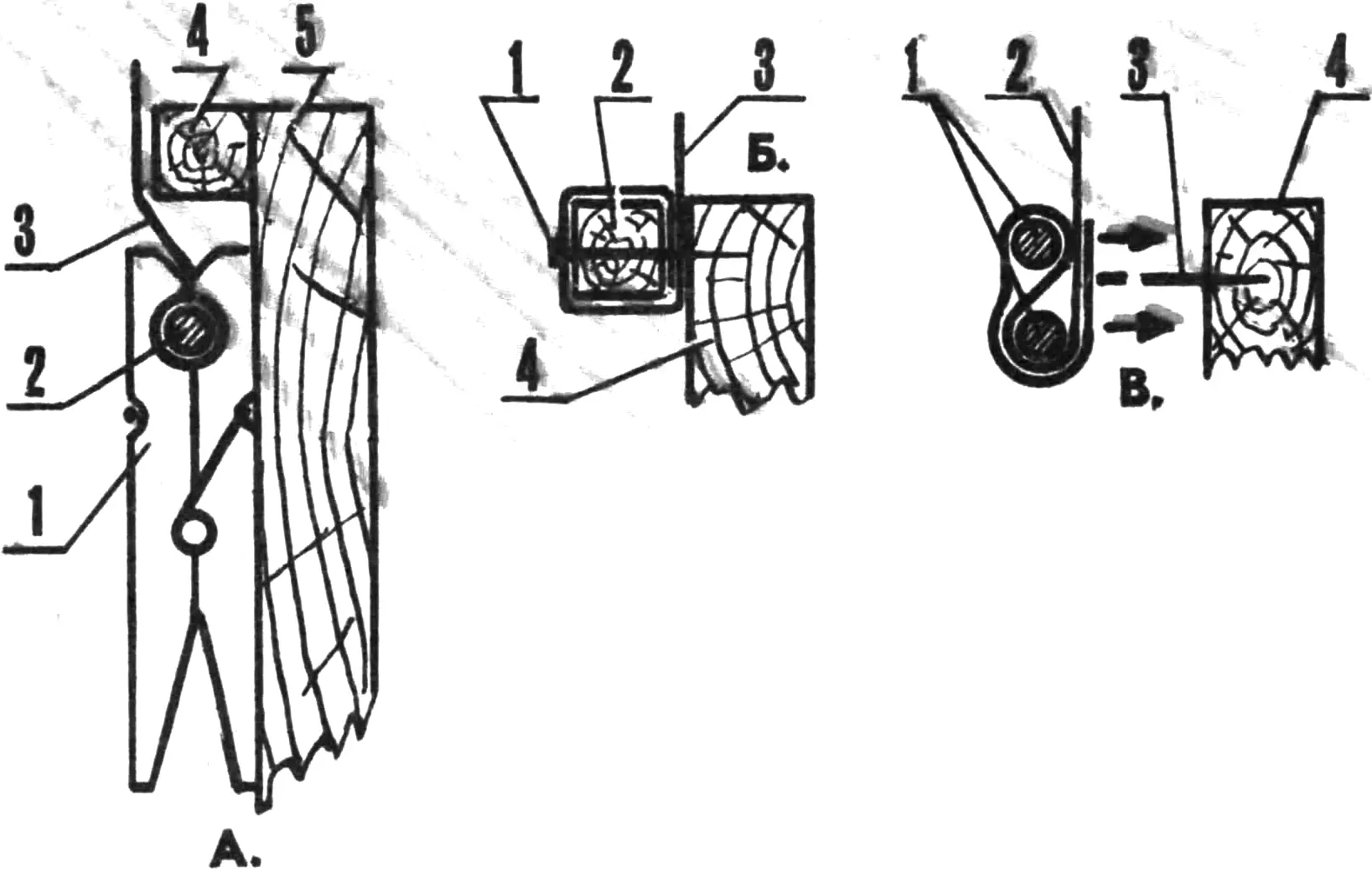
A — using clothes pegs: 1 — peg, 2 — metal rod, 3 — film, 4 — support (wooden batten 15X 15 mm cross-section), 5 — dryer base frame.
B — using a batten and nails: 1 — nail, 2 — batten 15X15 mm cross-section, 3 — film, 4 — dryer base frame.
C — using spikes and metal rods: 1 — metal rods, 2 — film, 3 — spike (headless nail), 4 — dryer base frame.
The transparent cover itself is welded from synthetic (for example, polyethylene) roll film. Two side panels are firmly attached to the main sheet, leaving an unsecured section of the main sheet on the north side of the dryer (about 100 mm) to form a ventilation gap. One must also provide for the following: a welded fold for subsequently reinforcing the crossbar in it — a section of pipe of the appropriate diameter (possibly from straightened gymnastic hoops) filled with sand.
Among existing methods of fastening the synthetic cover to the frame, the batten clamp, piercing the film edge folded between two metal rods onto headless nails driven every 200 mm, as well as a detachable connection using… clothes pegs have proved themselves well in practice. The latter can also be used to fix the crossbar at the required height, ensuring the set ventilation mode during drying.
To reduce friction of the film against the frame arches (and accordingly increase the service life of the transparent cover of the solar dryer), I recommend wrapping these metal elements with a strip of old film. Rubber bandages, from which the tension device is made, also contribute to the durability of the cover by ensuring constant tension of the film during sharp gusts of wind.
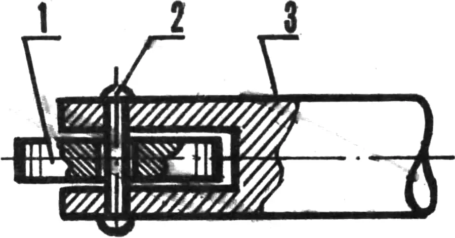
1 — welding roller (steel washer with knurling on the outer diameter), 2 — roller axle (rivet), 3 — fork (mounted in the electric soldering iron instead of the standard tip).
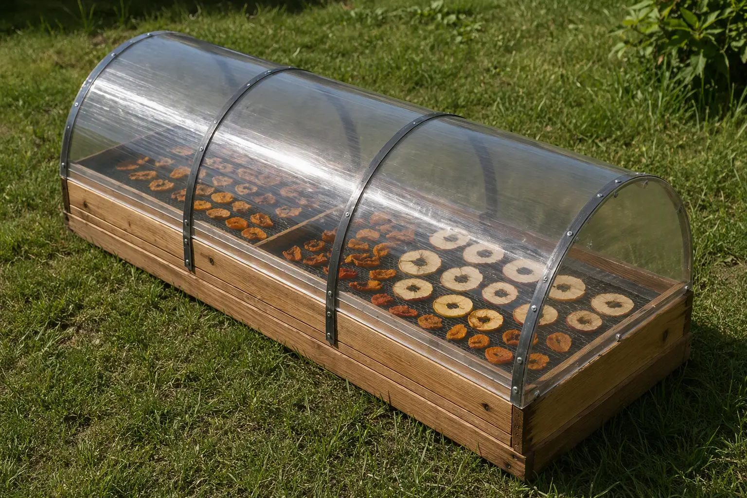
The solar dryer is placed on an inclined platform oriented to the south in order to make maximum use of the radiant flow of solar energy. The angle of inclination depends on the geographic latitude of the given area and for the country’s central zone is within 20…30°.
Pre-treated (blanching, sulfiting) raw material is placed inside the unit on spread paper (blackened, roll). Approximately 10—12 kg per square meter. Solar rays, passing through the transparent synthetic film, are absorbed by the products being dried. The operating mode is largely determined by the width of the ventilation gap, which regulates the intensity of air exchange.
The possibility of using the unit as a greenhouse in spring for growing early seedlings is not excluded.
«M-K» 9’91, S. LARKIN, Candidate of Agricultural Sciences
Recommend to read
 COZY CORNER
What can compare with the beauty of the gardens, with a unique fragrance of flowers and herbs, denounced by a light breeze? This time all the time you want to spend on the air.... DELTA – TOP COMPACT
our Readers probably know of noma abbreviation TX-200. It is the tan called autocritic original design created by the famous in the circles of avtomodelistov Kharkiv V. Taranukha, in...
