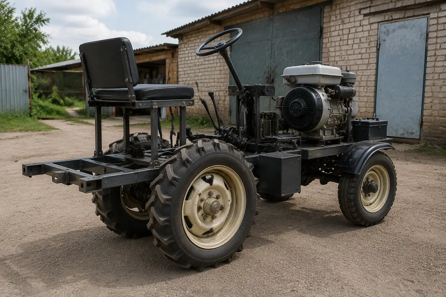
For more than a decade G. Malakhov has worked as the chief mechanic of the tool shop at one of Moscow’s aviation plants. But he has spent even more time (since the age of 13) on amateur technical creativity, without which he cannot imagine his present or his future at all. His record includes aerosleds, motorcycles, and other self-propelled machines. At present, life has forced Gennady Yuryevich to step away from his “specialty” — he has made several high-precision woodworking machines of various purposes, installed them next to his parents’ house in a village near Moscow, and supplies his fellow villagers and residents of the nearest dacha settlement with excellent lumber, which helps him and his large family survive. But he has not forgotten the main thing — next year he plans to assemble, without fail, a long-conceived amphibious vehicle with an air propeller drive. Today, however, the subject is a small tractor he made mainly from what had accumulated over many years in his garage.
From my teenage years I could not calmly pass by an engine that needed a good repair. All the time free from studies I spent in a garage or workshop where my fellow villager worked — a collective-farm mechanic of the old school. More than a dozen engines were restored by me under his guidance.
A little later the idea of independently building self-propelled equipment came. That is how my motorcycles, tricycles, aerosleds, and all-terrain vehicles on low-pressure pneumatics appeared. Not all of them represented the height of technical perfection, but most served their purpose, and my younger brother and his friends got a great deal of pleasure riding them. As for me, after something had been embodied in metal and brought to a finished state, thoughts of a new or more advanced machine would begin to haunt me.
In mature age, life forced me to take up the manufacture of more necessary units, including a mini-tractor for all kinds of work on a household plot. By that time I already had some experience in this field — a wheeled tractor had been built on the basis of units and assemblies from T-25 and T-40 tractors, but it turned out to be too large and heavy.
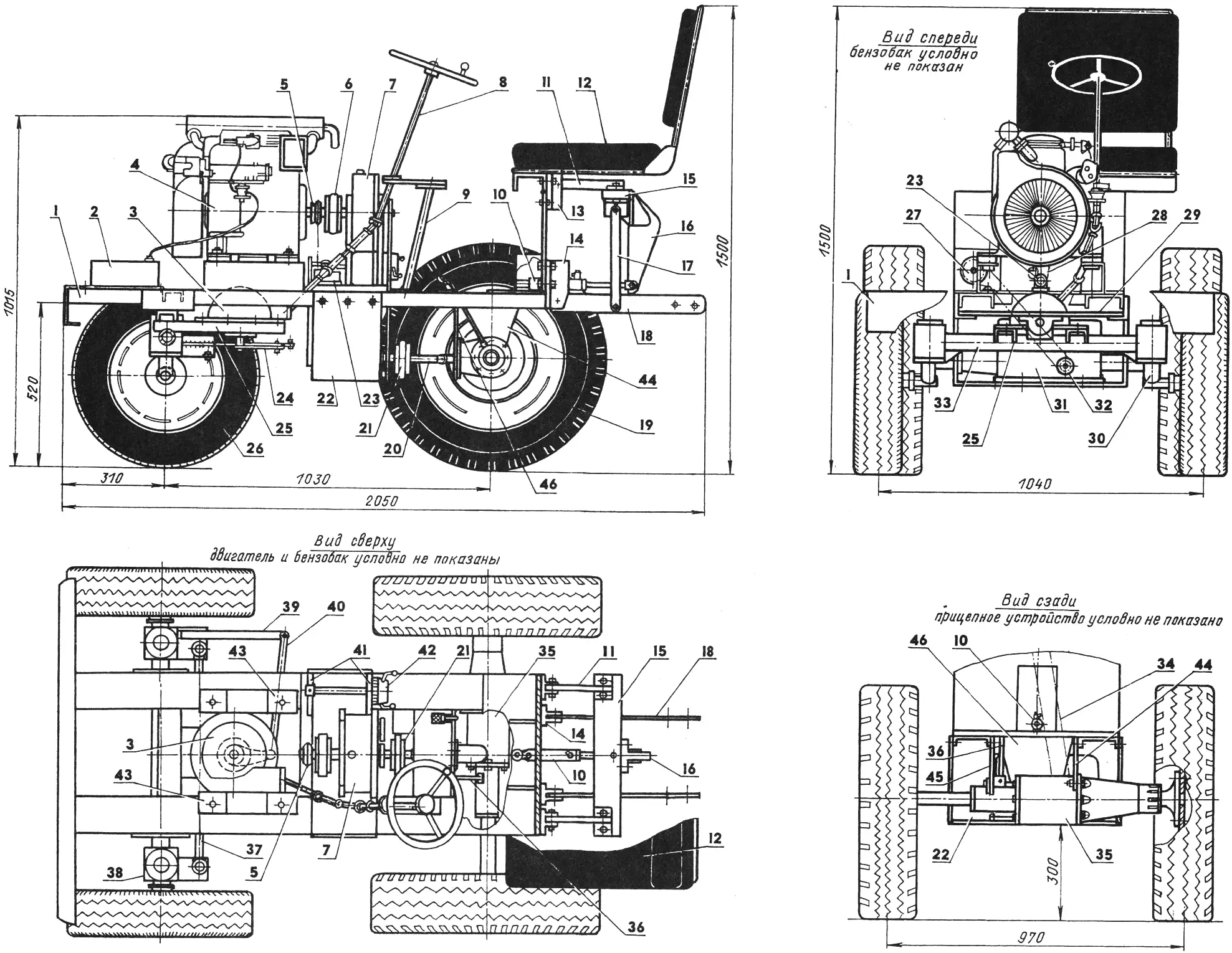
1 — frame; 2 — fuel tank; 3 — steering gear (worm gearbox from a metal-cutting machine); 4 — UD-8 engine; 5 — hydraulic pump drive pulley; 6 — flexible coupling (from a Zhiguli car); 7 — universal unit; 8 — steering shaft and transmission (from a ZIL-130 truck); 9 — steering column (St3, tube 42.3×2.8, L380); 10 — hydraulic cylinder (from a ZIL-130 truck); 11 — upper rockers (St3, strip 30×15, L220); 12 — seat; 13 — upper bracket (from farm machinery); 14 — lower brackets (from farm machinery); 15 — bar (St3, strip 60×25, L520); 16 — lever (St3, sheet s12); 17 — rod (St3, strip 20×12, L340, 2 pcs.); 18 — hitch bars (St3, strip 60×15, L500); 19 — rear wheel (from a UAZ-469); 20 — propeller shaft; 21 — flexible coupling (from a Ural truck); 22 — gearbox housing (D16T, sheet s12); 23 — hydraulic pump (from a ZIL-130 truck); 24 — steering arm (St3, sheet s10); 25 — left beam for mounting the steering gear (St3, channel 65×36, L410); 26 — front wheel (from a Zhiguli car); 27 — driving sprocket of the gear-shift mechanism (z = 20); 28 — hydraulic pump drive belt; 29 — front axle suspension beam; 30 — kingpin; 31 — gearbox (from a milling machine); 32 — driven sprocket of the gear-shift mechanism (z = 13); 33 — front axle beam (St3, tube 60×4, L600); 34 — transmission chain; 35 — rear axle reduction gear (angular helicopter gearbox); 36 — left-wheel engagement lever; 37 — adjustable transverse steering rod; 38 — bearing unit housing; 39 — longitudinal steering rod; 40 — transverse steering rod; 41 — brackets for mounting the gear selector (D16T, sheet s10); 42 — gear selector (from a metal-cutting machine); 43 — engine mounts (rubber, 4 pcs.); 44,45,46 — rear axle mounting brackets (St3, sheet s20)
For the “garden tractor,” the simplest design layout was chosen — a light welded frame of steel sections, on which all the machine’s main units and assemblies are mounted. The frame consists of two side members, a front crossmember, a rear crossmember with a center bracket for mounting the rear axle, a beam with an eye for the front axle suspension hinge, a platform for installing the universal unit, the gear selector and the hydraulic pump, and a seat base.
The oscillating front axle is fitted with a steering gear mounted on two channels welded to the axle beam. A propeller shaft runs from the steering wheel to the gear. The front wheels are turned through a system of rods and rockers.
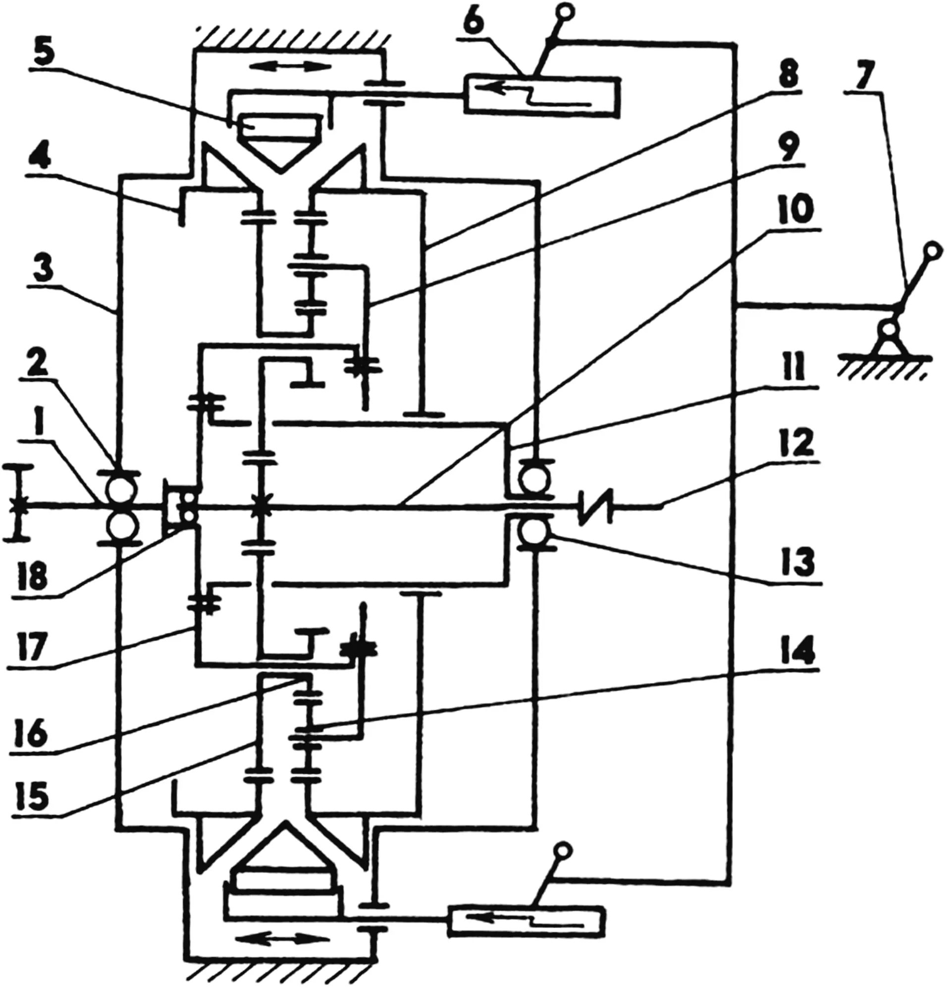
1 — output shaft; 2 — bearing 160209; 3 — housing; 4 — left sun gear (z = 57): 5 — pressure ring; 6 — rack mechanism; 7— “reverse—idle” control lever; 8 — right sun gear (z = 54); 9 — secondary carrier; 10 — input shaft with gear ring (z = 15); 11 — intermediate bushing; 12 — driving shaft; 13 — bearing 160208; 14 — idler gear (z= 15, 3 pcs.); 15 — larger planet gear (z = 21); 16 — smaller planet gear (z = 12); 17 — carrier; 18 — bearing 203
The rear axle, like the front one, has no springs or shock absorbers and is rigidly attached to the frame by two side brackets and a center bracket.
An 8 hp four-stroke 4-cylinder UD-8 engine with forced air cooling from a mobile power plant was used as the power unit. It has a number of advantages over other engines, offering good economy, exceptional quietness, and easy starting in any weather.
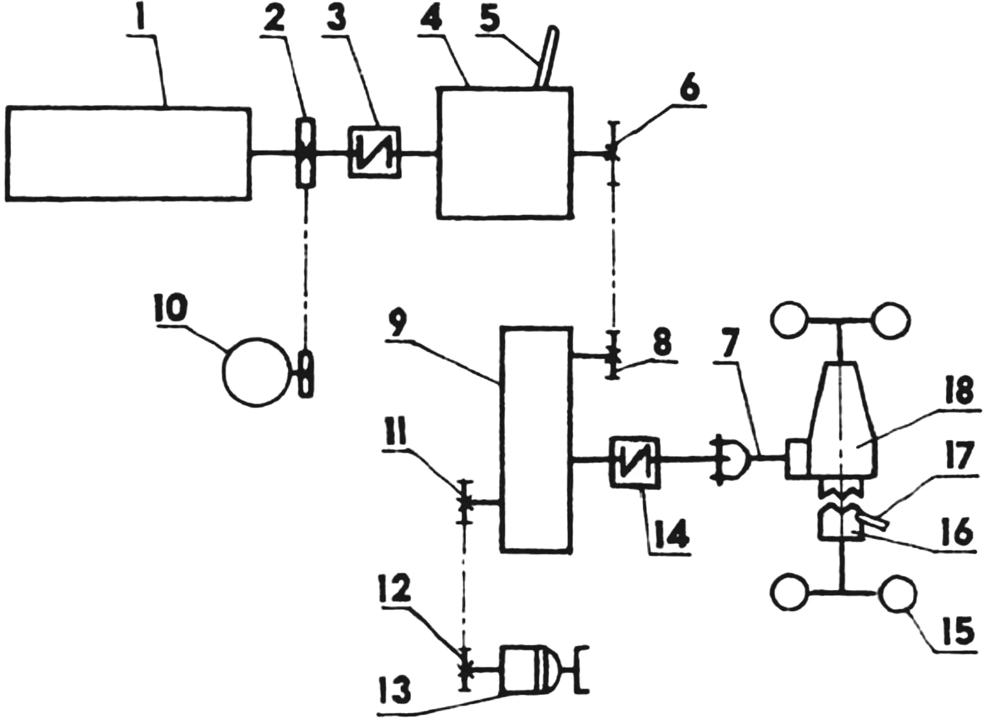
1 — engine; 2 — hydraulic pump drive pulley; 3,14 — flexible couplings; 4 — universal unit; 5 — “reverse — idle” control lever; 6 — driving sprocket (z = 16); 7 — propeller shaft; 8 — driven sprocket (z = 13); 9 — gearbox; 10 — hydraulic pump; 11 — driven gear-shift sprocket (z = 13); 12 — driving gear-shift sprocket (z = 20); 13 — gear selector; 15 — rear axle wheel; 16 — dog clutch; 17 — left-wheel engagement lever; 18 — rear axle reduction gear
The engine is mounted on four rubber-fabric dampers. Power take-off from the UD-8 output shaft is by belt drive to the hydraulic pump intended to drive the trailed implement, and through the transmission to the driven rear axle. Some weight penalty in the transmission due to using a gearbox and gear selector from a written-off milling machine is more than offset by the light universal unit and the rear axle reduction gear, for which a modified (if necessary a dog clutch for engaging the left wheel can be connected) angular tail-rotor gearbox of a helicopter was used.
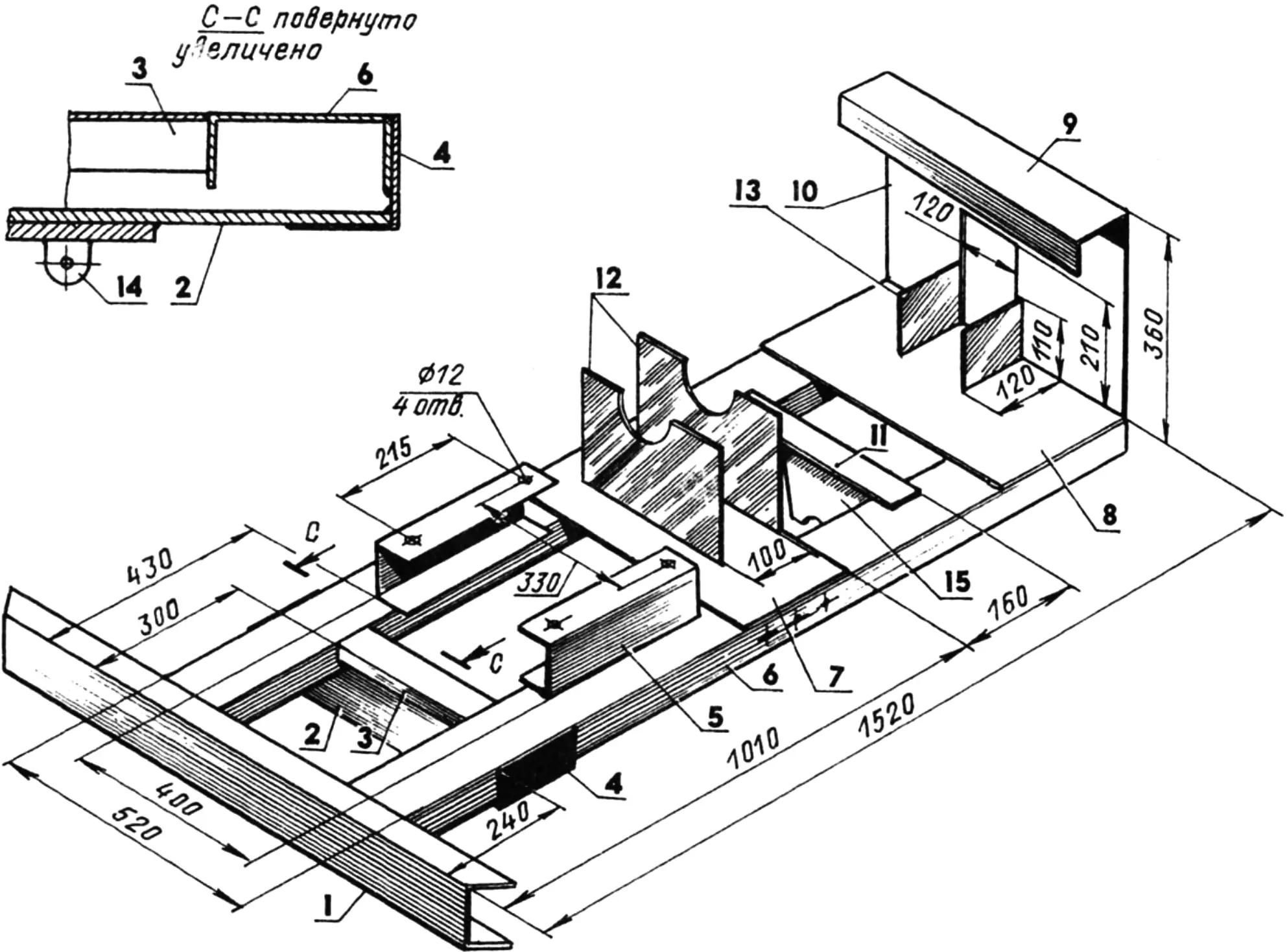
1 — bumper (channel 120×52); 2 — front axle suspension beam (strip 105×10, L520); 3 — front crossmember (channel 65×36, L280); 4 — bracket (angle 70x70x5, L125); 5 — engine support (channel 100×46, L315, 2 pcs.); 6 — side member (channel 120×52, L1515); 7 — platform (sheet 520×210, s15); 8 — seat base (sheet 520×200, s15); 9 — seat mounting beam (channel 100×46, L520); 10 — seat upright (sheet 520×308, s15); 11 — rear crossmember (sheet 400×130, s20); 12 — universal unit uprights (sheet 300×200, s15); 13 — gusset (sheet s20, 2 pcs.); 14 — eye of the oscillating hinge of the front axle suspension; 15 — center rear axle mounting bracket
The universal unit deserves a separate mention. It is a planetary reduction gear with two sun gears and an axially movable pressure ring between them. When the ring is shifted by means of a rack mechanism, the left or the right sun gear is braked. In the first case the gear ratio is in = 4.8 without changing the direction of rotation of the gearbox output shaft. When the right sun gear is braked, reverse (the tractor’s reverse gear) is engaged and the gear ratio increases to 7.3. If the ring is in an intermediate position, the engine runs at idle. The “reverse — idle” control lever is fitted with a simple three-position latch located on the unit housing. Thus the unit performs three functions: reduction gear, clutch, and travel-direction selector; and together with the gearbox (GB) it gives the tractor ten speeds forward and ten reverse, which is very convenient when working on different soils.
Structurally the unit is enclosed in a sealed housing. The carrier and the output shaft rotate in ball bearings, while the axes of the planet and idler gears run in bronze bushings that have grooves on the rubbing surfaces for oil flow. (Incidentally, 200—300 g of automotive transmission oil is poured into the housing.) The carrier consists of two parts joined by the planet gear axes. The output shaft is at the same time a support for the right sun gear, but their speeds and directions of rotation differ. Therefore there is an intermediate bronze bushing rigidly fixed to the carrier between them, and the engagement of the shaft’s gear ring with the larger rings of the planet gears takes place through slots in it. The clearance between the sun gears and the pressure ring is adjusted by moving the left gear along its axis by means of five screws.
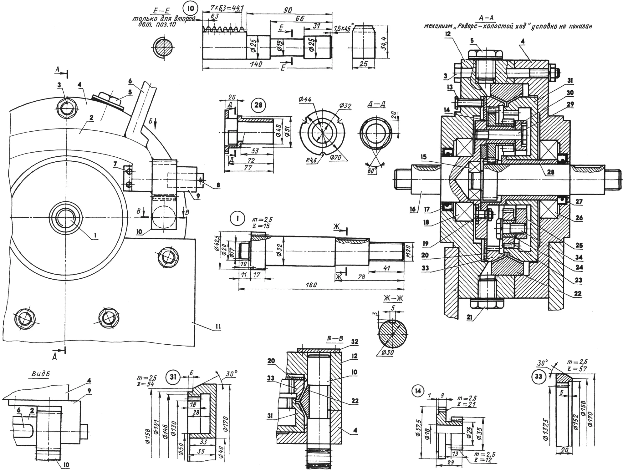
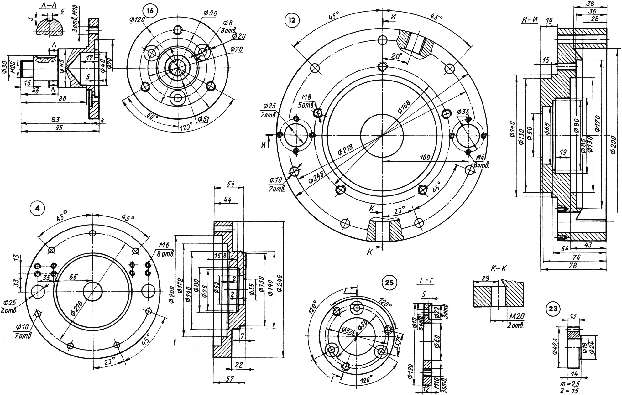
1 — driving shaft (30KhGSA); 2 — lever rocker (St3); 3 — clamp bolt M10 (7 pcs.); 4 — right half of the housing (D16T); 5 — filler plug (bolt M20); 6 — “reverse—idle” control lever (St3, bar Ø15); 7 — screw M6; 8 — control lever axle (St3, bar Ø15, 2 pcs.); 9 — bracket (St3, 2 pcs.); 10 — rack (30KhGSA, 2 pcs.); 11 — upright; 12 — left half of the housing (D16T); 13 — adjusting screw M8 (5 pcs.); 14 — planet gear(30KhGSA, 3 pcs.); 15 — bearing 203; 16,25 — carriers (30KhGSA); 17,27 — seals; 18 — bearing 160209; 19 — bolt M8 (3 pcs.); 20 — ring (bronze); 21 — drain plug (bolt M20); 22 — pressure ring (bronze); 23 — idler gear (z = 15, 3 pcs.); 24,30 — bushings (bronze); 26 — bearing 160208; 28 — intermediate bushing (bronze); 29 — planet gear axle (bolt M10, 3 pcs.); 31 —right sun gear (30KhGSA, z = 54); 32 — process plug (2 pcs.); 33 — left sun gear (30KhGSA, z = 57); 34 — bolt M10 (3 pcs.)
Two diametrically opposite slots are made in the pressure ring. The position of the ring relative to the sun gears is determined by the position of the racks (or rack rods) installed in special sockets of the unit housing and at the same time in the ring slots by the necks of their cylindrical parts, equal in length to the thickness of the pressure ring and in diameter to the slot width. When assembling the unit, only one rod is pre-mounted together with the right part of the housing, the sun gear, and the pressure ring. To install the second rod, part of its outer cylindrical collar 25 mm in diameter is cut down to 19 mm and inserted into the housing, after which it is turned 180° following final assembly.
In general this unit is intended for use in an amphibious vehicle with an air propeller drive, and for now one can say that it is being tested under “harsh” garden conditions.
“Modelist-Konstruktor” No. 4’2002, G. MALAKHOV
Recommend to read
 SCHEMATIC MODEL OF THE AIRFRAME
Before starting work, carefully examine the drawing and description. Then prepare the tools: small plane, a sharpened knife, pliers or pliers and a jig saw with saws. Materials you will... AUTOMATIC ACTIVATION OF PC SPEAKERS
As you know, speaker of the personal computer (PC) it is necessary to include separately. If they are installed at some distance from the operator, this situation is hardly comfortable,...
