THE PLOWMAN, AND THE TROOPER

THE PLOWMAN, AND THE DRIVERAlmost ten years ago bought a house with a plot of land in the village. The site must be processed, but without technology this work was daunting, and the money she had left. Here and was forced to build for these purposes, the tillers. Experience Amateur construction by that time I already had again, to travel to the village in the winter time made a “cane” snowmobile (remendously caterpillar). Tillers same though and have seen a lot (as industrial production and handmade), but he thereof built for the first time, so did many things as instinct. In the estimation of the tillers had become more a vehicle for the same trips and trucks and even all terrain, as part of the path to the village was a road which a road can be called only with great reserve.

Looking ahead, I note that the design has been quite successful: simple and reliable. Subsequently, I had built several of these tillers to order, and other craftsmen, including the guys from our club “modelist-Konstruktor”, in the construction of their machines took it as a model. The publication used pictures of several of them, so the performance of individual units may not coincide with the original design. But it can be used by those who want to repeat the design in their option.
 
With a choice of power units was not a problem — were available is not new, but serviceable engine from a motorcycle “IZH-Planeta-3”. He once purchased a bag, disassembled, but have proivisional and collected. Design capacity of 18 HP it is, of course, to provide could not, as his cylinder was already quite worn, but the strength is 15 — 16 he was issued.
To admit, and that was more than enough. From him as from the stove, and began to “dance”, although the specific alterations, in addition to equipment cylinder forced air cooling, it is not produced. Later replaced the valve on the radar — with characteristics of the engine changed for the better — easier start, markedly increased thrust, reduced fuel consumption, and the engine began to run smoother and quieter.
 
A major renovation had to be subjected to another unit — reducer. It, along with the main gear used from scooter cargo “the Ant”.
 
General view of the cultivator
 
General view of the cultivator:
 
1 — wheel (walk-behind “Cascade”, 2); 2 — drive shaft; 3 — reducer (of the scooter “Ant); 4 — engine mount (welded along 2 channel number 12); 5 — headlamp; 6 — front bracket-to-engine Motorama; 7 — damper; 8 — cylinder engine (from a motorcycle “IZH-Planeta-3”); 9 — crankcase (from a motorcycle “IZH-56”); 10 — blade valve; 11 — carb; 12 gearshift lever; 13 — air; 14 — shift lever; 15 — fuel tank (fire extinguisher); 16 — mounting brackets fuel tank steering levers; 17 — steering blocks (steel pipe Ø27, 2); 18 — rear view mirror; 19 — clutch lever; 20 — rear bracket-to-engine Motorama (steel, sheet s4); 21 — the lever of the control valve; 22 — brace (2 PCs.); 23 — the king pin hitch; 24 — case system forced air cooling cylinder (glass); 25 — wing-mudguard; 26 — thrust gear (ski pole); 27 — the lever throttle
 

Tying gear case
 
Tying gear case
 
The layout of the power unit (in the photo only the housing) of the motorcycle
 
The layout of the power unit (in the photo only the housing) of the motorcycle “IZH-Planeta-3” and gear from a cargo scooter “Ant” on Motorama (tensioning mechanism is not attached)

 
First, removed from the differential carrier satellites. Window Cup has expanded, cutting off the welding bridges between adjacent pairs of already existing Windows. A differential carrier seated on the shaft and welded using advanced Windows one detail to another.
 
Secondly, machined main drive shaft with a diameter of 30 mm for mounting cutters or wheels with axles in the middle part thereof by bearings 207 (replaced them 80207 — with side shields). At the ends of the shaft together with the wheel hubs, drilled holes into which inserted a cylindrical key — as it turned out, with intense and heavy exploitation diametrical bolts securing the wheel on the shaft, not stand — their cuts. At the ends of the shaft fulfilled the threaded holes (cavities) 10, each of which is screwed into a screw with a widened washer — it does not allow the dowel to fall out. Here I’ll note that the wheels from the tillers of industrial production “Cascade”. For teleoperative work put tubeless (hymatic) wheel size 5.00-10″, and for transport — pneumatic 6.00-12″.
Third, cut it from the gear case protruding outside of his ears half-sleeve. Themselves half Carter “besieged” on three sides (front, top and rear) strapping of steel rolling area with shelves 30×25 mm With strapping had to Tinker so tightly it fit, but now intensified and he dural Carter.
 
The shaft with the sprockets moved to the left side of the drive on the right. Mounting holes in the side plates (flanges) of the primary shaft of the gearbox are almost identical, except for some — they need to drill. Such a permutation could not do, but it simplified the transmission and given the opportunity to do without the intermediate shaft.
 
Kinematics of two-wheel tractor
 
Kinematics of walking tractor:
 
1 —the engine (from a motorcycle “IZH-Planeta-3”); 2 — box changes gear (transmission) power unit; 3 — secondary (output) shaft transmission; 4 — transmission output sprocket (regular “IZH-Planeta-3”); 5 chain gears; 6 — tensioning sprocket (nylon, from agricultural machinery); 7 — axis idler sprocket; 8 — input sprocket gear; 9 — the input shaft of the gearbox; 10 — reducer (motor scooter cargo “the Ant”); 11 — the drive shaft of the wheels; 12 — wheel (walk-behind “Cascade”)

 
The layout of the power unit and transmission tillers
 
The layout of the power unit and transmission of tillers:
 
1 — engine; 2 — the output sprocket output shaft of the engine; 3 — chain (t=15.875); 4 — motor; 5 — reducer; 6 — sprocket reducer; 7 — driven shaft of the gearbox (steel, circle Ø35); 8 — rail gear (area 30×30, 2 PCs.); 9 — strap tensioning mechanism (steel, sheet s4); 10 — sprocket tension mechanism; 11 — front mounting bracket of the engine; 12 — rear mounting bracket of the engine; 13 — pulley-head forced air cooling engine

 
Shaft reducer
 
Reducer shaft
 
Secondary reducer shaft (drive shaft of the wheels and cutters)
 
Secondary reducer shaft (drive shaft of the wheels and cutters)
 
The secondary shaft of the gearbox (drive shaft wheels and cutters)
 
Mill-cultivator of industrial production for self-made walk-behind tractor
 
Mill-cultivator of industrial production for self-made tillers
 
Pulley-head (anchor generator) system forced air cooling
 
Pulley-head (anchor generator) system forced air cooling:
 
1 — pulley-nozzle (steel, Ø 63); 2 — alternator; 3 — bolt M7 attachment pulley attachment to the anchor generator

 
Then moved to the arrangement mutual arrangement of the power unit and gearbox. But pre-manufactured mount (in fact, it can be used as the frame of all tillers). Motor mount is a square tube with a length of 600 mm welded from two segments channel number 12. On Motorama placed on top of the crankcase of the power unit and below it is docked to the gear housing so that drive shaft was located approximately in the middle of its length. Because of the distance from the planes of symmetry of the motor and reducer are different, the first had to displace about half an inch to the left (in the direction) side. The crankcase has pushed for more Motorama forward to slightly increase the distance between the stars of the transmission and install another one between them — a tension. In this place of transmission (between the asterisks to the power unit and gearbox) to increase traction, it would be possible to install the intermediate shaft (sometimes called the “homenethelp”). But my tillers acceptable overall gear ratio “displayed” through the use of the gearbox from “IZH-56”, and the engine power too much.
 
After reconciliation, the mutual arrangement in the same plane of the output sprocket of the engine (sprocket output shaft of the power unit) and the input sprocket gear to Motorama welded strapping halves of the crankcase and to fasten on motorhome power unit — brackets-ears of steel 4 mm sheet, full in the form of a stamped channel. Engine mount mounted on the engine crankcase, turned and welded it to the brackets. At the place I drilled the bracket mounting holes. Actually, if the mounting brackets of the engine to run not the usual holes and elongated slots, it is possible to do without the idler sprocket and tighten the chain — shifting of the engine relative to the motor, simplifying the design of the transmission.
 
After the layout of the main units began to design other fastenings: control levers, tractor mounted and trailed devices. Control levers (made of thick-walled pipe with outer diameter 27 mm) are screwed to the rear bracket of the power unit and supported by struts. And at the later levers secured on the racks of the fuel tank. Back to Motorama welded the drag hook is part travostino device of walk-behind cart. The drag hook is for hanging teleoperative tools: plow, cultivators, etc. Ahead to Motorama welded a pin for the mounting of the ballast plates, which increases grip on the road rascisim or with the soil in the processing of landings in the area.
 
As noted in the beginning of the article, the engine cylinder equipped with forced air cooling. Impeller centrifugal type, from the salon of an oven of the car UAZ. The drive of the impeller — through the belt drive pulleys with a ratio of 1. Drive pulley mounted on the generator rotor. As the belt is used a rubber ring (“belts”), cut off from the chamber of a motorcycle “IZH” — it does not require tension and can be easily removed to disable the drive in the cool weather. Cover vykleili of fiberglass epoxy binder pre-made wire frame. He (casing) — quick-detachable, is attached to the cylinder by two springs. But it should be recognized that the impeller is not fully ensures the cooling of the cylinder in extreme conditions when driving in the lower gears, but because planning to replace her.
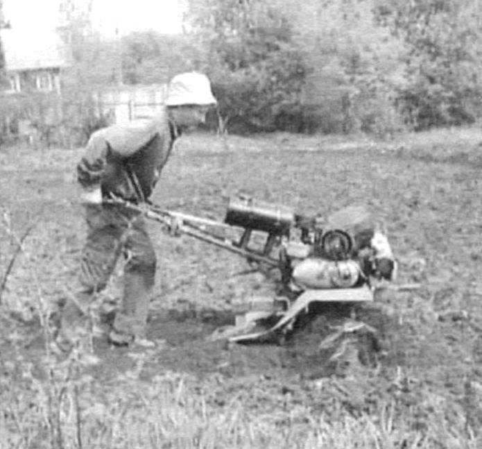
Mills (two of them) too, he did not do, and, like the wheels, bought the factory, “the Lancet,” or, differently — “crow’s feet” — they do local Perm plant for walk-behind “Cascade”. Hub cutters — thick-walled pipe with an internal diameter of 30 mm — without alterations must be mounted on the shaft of my walk-behind because the shaft I under them and grind. Fixed cutters on the shaft by two bolts each, through the respective through-holes in both parts. The diameter of Oltenia cutters for “arrows” is 350 mm. Each equipped with four rows of legs (three legs in a row). And it should be noted that these cutters were satisfied: they crushed the weeds and throw them to the surface (though sometimes wound), not buried in the ground and go smoothly. Even conducted an experiment: working walk-behind tractor was released into the “free floating” along a 50-meter plot, and he alone is normally plowed (cultivated) without turning anywhere. Design similar, but homemade cutters repeatedly cited in the journal “modelist-Konstruktor” and therefore give only photos, no drawings. Width under cultivation extension shaft — up to 900 mm.
 
In addition to “pointed” cutters adapted, prepared or manufactured and other teleoperative tools: the plow, Hiller, cultivator, kartoffelpuffer.
 
A minimum rate of tillers of about 5 km/h At that speed produce ploughing, cultivation, digging potatoes.
 
The ignition on the engine put e — motorcycle “Voskhod”. The cultivator was equipped with the track spotlight.
 
Because the tillers just intended as metamagic, manufactured trailer cargo single axle truck with a body capacity of up to half a ton and double seat. To make a soft sofa with back is also not too difficult, but then it would be impossible to carry long loads, and sometimes you have to transport the logs up to a length of six meters. However, the back is easy to do removable. Drawbar trailer are made of rectangular tube section 50×40 mm with a 2.5 mm wall. It is supported by two angle struts from corner No. 4.
 
Tow hitch is a simple but reliable pivot type. Bodywork truck with dimensions in plan, mm 1200×1200 — wooden boards — boards-lining 16 mm thick, the floor boards are twenty-coated steel 1.5 mm sheet.
 
Walk-behind Hiller of the disk cultivating mills
 
The walk-behind Hiller of the disk cultivating mills
 
Trailer single-axle cargo truck
 
Trailer single-axle cargo truck:
 
1 — the towing device; 2 — pole (steel tube 50×40); 3 — beam drawbar (angle steel 40×40,2); 4 — trunk (sheet s1,5); 5 — body (Board, wall paneling s16); 6 — wing wheels (from a motorcycle “IZH-56”); 7 — frame body (from a motorcycle “IZH-56”); 8 — wheel truck (from a motorcycle “IZH-56”); 9 — seat boot lid (Board s20); 10 — Paul (Board s20); 11 — the floor of the truck (sheet s1)

 
Node coupling truck
 
The site hitch truck:
 
1 — pivot bushing (pipe Ø50×30); 2 — plate (steel sheet s4, 2); 3 — swivel (steel, circle Ø45); 4 — swivel bushing (pipe Ø50×30); 5 — beam drawbar; 6 — pole

 
A very important node in the trailer behind tractor hitch. Its design may be different, but the reliability needs to be ensured. It also has to allow the trailer to turn relative to the cultivator, not only in the horizontal plane but limited vertical sector to prevent a runaway truck wheel. In photos variants of the devices
 
A very important node in the trailer behind tractor hitch. Its design may be different, but the reliability needs to be ensured. It also has to allow the trailer to turn relative to the cultivator, not only in the horizontal plane but limited vertical sector to prevent a runaway truck wheel. In photos variants of the devices
 
A very important Assembly of the trailer behind tractor hitch. Its design may be different, but the reliability needs to be ensured. It also has to allow the trailer to turn relative to the cultivator, not only in the horizontal plane but limited vertical sector to prevent a runaway truck wheel. In photos variants of the devices
 
Even impassable places are not an obstacle for the
 
Even the impenetrable space are not an obstacle for the “luxury” of walking tractor and truck
 
Walk-behind tractor in the transport version with a cargo trailer single axle truck, manufactured on the chassis of the two side trailers motorcycle
 
The cultivator in the transport version with a cargo trailer single axle truck, manufactured on the chassis of the two side trailers motorcycle “IZH-56”
 
Truck chassis with a wheel track of 1500 mm are assembled from two side trailers from a motorcycle “IZH”. The wheels are also from him. Their suspension is a torsion, soft, so drive a tandem “behind tractor — trolley” 60 — 70 km on a relatively flat field road is easy. To the speed of 50 km/h tandem controllable. The season rolled on it 3 — 4 thousand kilometres in the forest for firewood, in the field of hay (that’s just to mow it is not “taught”) and fishing. A very important Assembly of the trailer and walk-behind — trailer hitch. Its design may be different, but reliable. It also has to allow the trailer to turn relative to the cultivator, not only in the horizontal plane but limited vertical sector to prevent a runaway truck wheel. Total length of trailer truck — 2.5 meters.
 
Due to the power of the engine, locked the wheels, clad in the tires with large tread type “tree”, speed walk-behind tractor with towed truck was a jeep, so using it from early spring to late autumn. Some road (or rather off-road) situations and helps emerging due to the gearbox reverse gear. Wheel shaft, or rather their hubs are fixed with two bolts. But the ruthless exploitation of the tillers of the bolts are not times cut. Therefore, in addition secured them from turning on the shaft even longitudinal cylindrical dowels.
 
The tillers have become an irreplaceable assistant in the garden and in agriculture.
 
During the operation touched only the gearbox increased backlash in bearings. . — Season two was still possible to ride.
 
R. AKHMETZYANOV, S. Siva, Perm Krai

Recommend to read

  • STARTER FOR REZINOMOTORNAYASTARTER FOR REZINOMOTORNAYA
    In the circle model airplanes syut city of INTA has designed an electric starter for starting resinator indoor models. He performed well at the national competition at the indoor model...
  • WINDING MACHINE-AUTOMATICWINDING MACHINE-AUTOMATIC
    Once his hands were wound transformer coils, he knows how difficult, unproductive and laborious this work. It is necessary not only to carefully, turn to turn, put the wire on the frame,...