Of the essential features of the mechanism I note first of all the use of relatively powerful powerplant — engine from scooter “Tourist” with forced cooling (drive chain transmission — increments of 19 mm). Steering wheel standard motorcycle — this gave the tillers compact and familiarity in management: advantage, while moving in the transport version. And finally, the main distinctive feature is the braking system. Tell more about it.
When plowing with the help of cutters of various soil — loose or dense, and when working on slopes up or down, requires a different braking, as in these circumstances, mills develop different traction. On loose soil, it is less and virgin — very solid. In the latter case, without an effective braking of the cutter will not have time to bury, and plowing will be of poor quality, superficial. The same is observed when ploughing on the slopes: down inhibition should be much larger than that in upward direction. And the steeper the surface, the greater the difference. All this forced me to equip the cultivator with a special device — a brake that allows you to quickly change the detaining force when the rotation of the cutters. Is this effect due to the change in “angle of attack” of the main element of the device is zaglubljajutsja in-ground knife. However, in some cases, when working on very loose soils or for turns at the edge of the area, the braking is generally not necessary. Keep in these cases, the tillers on the weight, lifting the knife, it would be awkward and tiring. Therefore, the braking device allows a quick (literally 1-2) replace the blade for extra support wheel. In addition, the proposed scheme site provides the ability to install instead of the brake blade or mouldboard cultivator, with which it is possible to carry out the same manipulations.
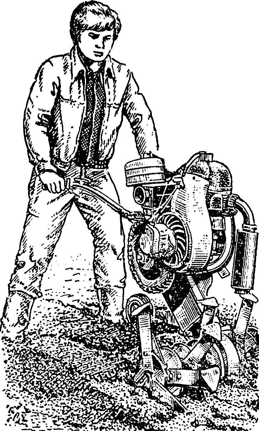
Motoblock “Arsen”:
1 — engine, 2 — tank, 3 — wheel, 4 — magneto 5 — sprocket Z = 44 of the intermediate shaft 6 — the bearing housing of the intermediate shaft (2 PCs), 7 — the transmission housing, 8 — the working shaft, 9 — brake 10 — Bush cutter, 11 — flange mill, 12 — knife cutter, 13 — grip shifter, 14 — under engine bracket, 15 — muffler, 16 — working on (plow). Cooling jacket on the left view conditionally withdrawn.
And now briefly about the main units of the unit-the motoblock “Arsen”.
The engine power of 11.5 BHP with forced cooling. Instead of a battery ignition I have installed magneto — this system is simpler and more reliable. Homemade silencer, vortex ejection type, made according to the drawings published in the magazine “Inventor and rationalizer”, No. 9 for 1980. Arm gear shift also homemade, from a staff used only the quarter slots.
To ensure the passage of the chain in the lower part of the gearbox had to be partly cut collar.
Transmission is a two-stage chain transmission: the first stage has a sprocket Z = 8 and Z = 44, the second Z = 11 and Z = 25. All stars (except homemade Z = 8, disposed on the output shaft of the gearbox) standard, under a chain with a pitch of 19 mm. the Intermediate shaft was first mounted in two bearings located on one side relative to the small sprocket, as it did on matarese G. A. Kuznetsov from Moscow (see “M-K” No. 10 of 1983). This scheme is simple and easy to adjust chain tension, but the operation demonstrated the unreliability of this attachment: bearings quickly failed. Had this node to alter, by installing the bearings on both sides of the small sprocket. The result is an intermediate shaft for a long time it works every time.
Intermediate shaft Assembly:
1 — the transmission housing, 2 — bearing housing (2 PCs), 3 — the bearing № 206 (2 PCs), 4 — sprocket Z = 44, 5, 12 — cap bearing housings, 6 — bushing sprocket (the hole for the lock bolt M10 conventionally not shown), 7 — bolt M8 (6 PCs.), 8 — key 8X8X40, 9 — intermediate shaft 10 — bolt M10, 11 — retaining pin bearing housing M8 (8 PCs.), 13 — retaining ring (2 PCs.) 14 — dowel 8Х8Х30, 15 — sprocket Z = 11.
The transmission housing welded, made from sheet steel with a thickness of 4 mm. In the upper and lower parts provided with holes for bearing axle boxes of the working and intermediate shafts. On top of the casing is welded an l-shaped bracket under the fuel tank chainsaw “Friendship” (you can use any other) and the box-shaped socket for motorcycle steering. The latter is secured by two M10 bolts. On the rear (in the direction) wall of the transmission housing has a coupling device for connection with the carrier truck: the segments of area and square tube with holes for pins Ø 16 and 25 mm. To the front wall of the transmission housing under engine bracket is welded from thick-walled tubes with a diameter of 44 mm. the working shaft is mounted in bearings No. 308, and one of the bearing housings are welded, and the other fastened with screws M6. The exposed portion of the working shaft throughout their length have a keyway 5X10 mm.
The bearing housing of the working shaft with the cover.
Cutter tillers consists of a sleeve secured inside the spigot, flanges 4 and 12 knives T-shaped. The knives are attached to the flanges with bolts M10 with an offset of 30° for each subsequent flange in relation to the previous one. My chosen form of blades in the form of hoes, in my opinion, more comfortable than the widely used G-shaped: they are easier to deepened into the soil and due to even distribution of loads have no tendency to curl. Plowing width — 600 mm, depth — 230 mm.
Knife cutter.
The wheels used are standard, from scooter “Tourist”, but have improvised and hub roller clutch overtaking.
Brake tillers. Design it is clear from the drawing, but here we need to make a few additions. The axis of the brake blade — stepped shape, so almost identical to the cheeks, drilled holes under the axis of different diameters 10 and 14 mm. square Tube made of parts of old metal beds. Each latch fixed to the brake axle and the knife pressed U-shaped spring. The handle is an oval metal ring of arbitrary size. Support wheel mounted on the axis of two racks attached to the cheeks with bolts M10.
The sleeve is screwed into inner tube screw-M36 and is fixed by screws M8.
Brake:
1 — brake knife, 2 — spring retainer 3 — retainer (2 PCs.), 4 — arm latch (2 PCs), 5 — arm retainer rotator spring, 6 — handle, 7 — support wheel 8 — axle brake knife, 9 — the case of the retainer 10 — cover 11 — outer pipe rotator, 12 — bushing, 13 — pipe of square cross section, 14 — bolt M10, 15 — cheek (2 PCs.), 16 — axis of the retainer, 17 — inner tube rotator, 18 stopper, 19 — M6 screws (6 PCs.). On items 12 and 17 holes for the lock bolt M10 conventionally not shown.
Quick change of brake knife on the wheel is due to the rotation of the braking device 180°. To this end drive inner pipe done two diametrical openings, one of which includes a spring loaded stopper.
All brake device is attached to the transmission housing with two bolts M10, to which a rectangular pipe is welded two nuts. As one of the bolts goes through a hole, Ø 25 mm, it is necessary to wear the appropriate size washer.
Towed truck home-made, designed to transport 300 kg of cargo. Body length 1000, width 950 and height — 300 mm. Wheels and the shock absorbers are also from the scooter. The frame is made from parts of old metal beds, carrier — segments of water pipes. The sides and bottom of hardwood, tailgate folding. Seat taken from bike. The wheels are equipped with brake treadle. The coupling device includes a T-shaped pin that is installed in the pipe on the bearings. This design turns the tillers of the vehicle with articulated frame that can move with the speed of 20 km/h.
Motoblock “Arsen” pneumatic tires go with the truck.
In conclusion, I want to share some thoughts on design improvements. Particularly in the bearing housings of the intermediate and working shafts, it is desirable to set the seals, to completely eliminate the possibility of ingress of moisture and dust. The transmission housing is necessary to provide a viewing window to monitor the chain tension and also the filler and drain holes for liquid lubricant. The working shaft can be shortened: for example, 400 instead of 600 mm. Then it will not interfere with the hilling. Every hub cutter is enough to set 3 flange and, respectively, 9 blades, increasing the width of their base. However, in this case the track of the tow wheels of the trolley need to post up to 1.5 m to provide satisfactory cornering stability when driving on the road.
V. MESHKOV, Arsenyev, Primorsky Krai
Recommend to read PRESS THE BIBLIOPHILE In every family there is not one book, which is read, that is, to the holes. We carefully stored the logs of past years for the sake of one or two written in them of favorite pieces.... BUILDING A CAR When vehicle type is defined: scheduled its approximate dimensions, weight, number of seats in the back, the engine, comes perhaps the most important stage of design development of the... 
 Getting the design of this machine, I proceeded above all from the conditions of its future work. The soil in our area is mostly heavy loam, stones… and surface plots are far from perfectly smooth. In short, the operation was not easy. This fact determined the choice of the main parameters of the mechanism.