WALK-BEHIND-TRUCK

BEHIND TRACTOR-TRUCKOffer to readers design their new walk-behind. But before describing it, a little background. Village life is hard their daily monotonous work in summer and winter, rain and snow… Wanted to do something to alleviate all this work and care. I did a walk-behind tractor. And not generic, as usual, with a cart, because more needed in the vehicle. For the relative small size called it a “Humpbacked”.


The photo shows the first, not the upgraded version of the tillers.
 
Please note: the cart was loaded with bricks. Moreover, in the summer I put it in the cart three two hundred liter barrels of water for watering the garden. This is 600 kg with odd! In my opinion, good payload.
 
On the bogie applied to the wheel from the vehicle G AZ-69, others get failed. And well: because of their large diameter these wheels have less resistance to movement.
What are the advantages? The small dimensions. Good driving dynamics at speeds from 5 to 35 km/h (at engine speed 5500 engine rpm). Maneuverability: you can turn on a “dime”. Efficiency. The simplicity and reliability. Low maintenance: the application of most of the nodes are a sealed bearing 180205Е allowed to opt out of the grease.
 
Layout walking tractor
 
Layout walking tractor:
 
1—the engine (from a motorcycle MMVZ-Z. 111); 2 — air filter (MMVZ-3.111); 3 — ignition coil (B-300); 4 — lever the reverse-reducer; 5 — the lever of the transmission control of the engine; 6 — brake pedal; 7 — a muffler (from the m II pumps-800); 8 —frame walking tractor; 9 — mud flap; 10 — node hinge; 11 —frame truck; 12 — the brake cylinder; 13 —body of trolley; 14 — the switch (CAT-1A); 15 — fuel tank (from a moped “Riga-12”); 16 — grip throttle; 17 — seat; 18 —clutch lever; 19 — wing; 20 — lock lever engine starting, rubber; 21 — the lever start the engine.

 
Transmission of two-wheel tractor
Transmission of tillers:
 
1 — engine sprocket (z = 14); 2 — reducer chain t = 12,7); 3 — reverse-gear reducer (I = 1,64); 4 — sprocket shaft (z = 40); 5 — an asterisk of a secondary shaft (z = 18); 6 — circuit chassis (t = 19,05); 7 — sprocket undercarriage shaft (z = 27); 8 — shaft chassis.
 
Bracket gearbox

 
Bracket gearbox.
 
Frame walking tractor
 
Frame walk-behind:
 
1 — the frame of the engine (the part of the frame of motorcycle MMVZ-Z. 111); 2 — the eye (the sheet s10, 2); 3 — tripod mount frame control (tube 30×6,5, 2 PCs); 4 — bracket frame control (sheet s7); 5 — eyelet wing (sheet s7, 2); 6 — holders (sheet s5); 7 — housing hinge Assembly: 8 — bar (pipe 43×26); 9 — longitudinal (pipe 43×43, 2); 10 — cross member (tube 43×26); 11 — Klondike (50×50, leaf s); 12 — axle mounting of the muffler (pipe 12×2).


Node chain tension
Node chain tension:
 
1 —the frame of the cultivator; 2 — bracket reverse-reduction gear; 3 — bolt М14х1,5 chain tension gearbox; 4 —lock nuts М14х1,5; 5 — bracket axle, left; 6 —bolt M 16×1,5 lock; 7 — nut М14х1,5 tension of the crawler chain (2 PCs).

 
Control unit
 
Control unit:
 
1 — lever start the engine; 2 — a lock lever (rubber); 3,8 — rod; 4 — reverse gear; 5 — bar levers; 6 —control lever reverse gear; 7 — the lever of the transmission control of the engine; 9 — the lever roller gear box; 10 — engine.
 
Bar arm

 
Bar levers:
 
1 —bracket; 2 — a shaft of levers (finger (finger Ø8); 3 — carriage with a control lever reverse gear; 4 — a small carriage with a lever gearbox of the engine.
 
Bridge walking tractor
 
Bridge walking tractor:
 
1 —nut M 18×1,5; 2 — hub left (sprocket z = 29, t = 19,05); 3 — prismatic shear (30x8x7); 4 — spacer; 5 — body suspension shaft; 6 — a lock ring; 7 — ’ 180205Е bearing; 8 — shaft chassis; 9— hub right.


Engine walk-behind — motorcycle MMVZ-111 C with forced air cooling, contact-oil Vozduhoflotsky and carb-TO-36C. The power supply system of the engine is simple and consists of a fuel tank from a moped “Riga-12”, regular benzocane CU-12 and tubing of the fuel pipe.

 
Transmission. From the drive sprocket (number of teeth z = 14) the main transmission of the engine torque chain PR-12,7 is transmitted to the driven sprocket (z = 40) gearbox. The last is taken from the boat motor CM-500V. On the output shaft reverse gear (its the gear ratio 1:1,64) sits the star (z = 18), from which the torque circuit PR-19,05 is transmitted to the sprocket (z = 27); she is the drive shaft and axle, respectively, the wheels of the cultivator.
The engine and entire powertrain are mounted on a frame tillers collected mainly from steel pipes square (43×43 mm) and rectangular (43×26 mm) sections using lectropol welding. The front, the crossmember, welded in a curved pipe with a diameter of 27 mm (the standard frame of motorcycle MMVZ-Z. 111) with nodes installation of the engine, reinforced by two triangular gussets and provided with tubular through-axle for mounting the muffler.
 
The cross member has at the ends two eye — steel hinges for towing behind tractor and attach some implements, for example, dozer blade.
 
The sides of the spars vertically welded to short sections of pipe — Jack under the front tips of the frame control. The rear tip of the frame is screwed to the bracket on the crossbar.
 
The rear frame of the cultivator is equipped eyelets mounting fenders and body hinge Assembly, which joins two-wheel tractor trolley.
 
Welds sanded, and where possible — processed files. All components and parts, primed and painted a bright color.
 
In the middle of the spars have holes for locking bolts M16 fastening node chain tension. The node — shaped bracket, welded from sheet steel. On top of it being installed and bolted with five screws M14 reverse gear. The M14 bolt the tension of the chain running from the engine to the reverse gear inserted into the hole in the crossbar and two sides fixed by lock nuts.

 
The necessary degree of chain tension, although the years of exploitation of the tillers showed a rare need for such operations, I seek in the following order. Loosen retaining bolts M16. Turning the nut on the M14 bolts welded to the housing shaft of the chassis, pull the chassis circuit. Then the nuts on bolt M14 curly bracket adjust chain tension gearbox. After this the retaining bolts are tightened.
 
The bridge is a combination of body and chassis of the shaft. The shaft housing is welded from a cylindrical holder, two brackets with slotted holes 70×16 mm and two M14 bolts.
 
Running the shaft rotates in two bearings 180205Е, from axial displacement to hold the two locking rings. At the ends of the shaft are the hubs of the wheels, the left one with the sprocket driven by the gearbox. Hub nuts with attached lock washers.
 
The controls consist of two units: lower and upper. The bottom includes a lever starting the engine, held in the transport position, the rubber retainer on the casing of the engine cooling, as well as leverage the re-vers-reducer and gearbox, which are located on the panel, screwed to the body of the gearbox. The last two of the switch lever by the driver’s legs “humpbacked”.
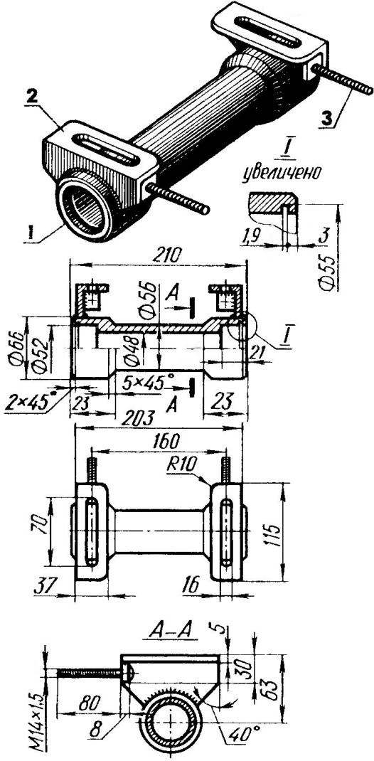
 
Housing chassis shaft
 
Body chassis shaft:
 
1 — ferrule; 2 — bracket; 3 — bolt М14х1.5 chain tension gearbox.
 
Frame control two-wheel tractor
 
Frame control tillers:
 
1 —tip thread М16х1,5 mounting frame (2); 2 — rod (pipe 21×2, 2); 3 — hinge wing mounting (2 PCs); 4 — mounting bracket ignition coil; 5 — eyelet electronic switch (2); 6 — bracket fastenings of a fuel tank; 7 — arc (tube 14×2); 8—grip throttle; 9 — the bar top with the mounting holes of the fuel tank; 10—spacer (tube 14×2); 11—clutch lever; 12 — backup (pipe 18×2); 13 — tip threaded 14×1,5 mounting frame; 14 — the crossbar of the lower (pipe 18×2).
 
Mount the fuel tank:

 
Mount the fuel tank:
 
1 — tank; 2 — piping welded flange of the tank (rubber); 3 — earring push-on; 4 — screw M6 (2 pieces); 5 — bracket tank frame control; 6 —frame of the cultivator.
 
Wing walk-behind tractor (shown left-right — mirrored view)

 
Wing walk-behind tractor (shown left and right — mirrored):
 
1 — the support for feet of the driver (rod Ø8); 2 — wing (steel sheet 1,5 s); 3 — slip Mat (corrugated rubber); 4 — a bolt M5 (4x); 5 — bracket of the front; 6 — back bracket; 7 — liner front-side (wire Ø3); 8 — liner rear (rod Ø8).
 
Hinge joint (top view, the plug is conventionally rotated)


Hinge joint (top view, the plug is conventionally rotated):
 
] —nut M24; 2 — spacer; 3 — the case of the hinge Assembly; 4 bearing 180205Е (2); 5 — plug; 6 — washer; 7 — axle; 8 — frame walk-behind tractor.


Upper unit is a control frame, welded from pipes of different diameter. Rod frame is equipped with handles (including handle “gas”) and the clutch lever. For them, the driver of “humpbacked” holds hands. In addition, the frame has different mounting device, which is attached to it fuel tank, ignition coil, electronic switch and rear ends of the wings. And again, on the right side of the drawbar of the cargo truck in a small corrugated pad is the brake pedal (but more on that later).
 
The cultivator is applied, after small alterations, the exhaust from the fire pump MP-800. It welded the exhaust pipe of the engine, with mounting flange. On top of the muffler are welded two eyelets for attachment to the axles of the motor frame bolt M8.
 
Wings “humpbacked” have an unusual shape. Covering them is made of steel sheet 1.5 mm thick. the Edges are reinforced rolled them with wire of different diameters. Contact of Shoe soles of the driver with wings covered with rubber mats. To keep the driver’s feet from slipping down, there are special stops. For greater rigidity to the hull inside G welded brackets. Fasten the wings to the frame control (front) and frame tillers (rear) each with two bolts M10. In addition, they have rubber mud flaps.
 
After heavy use in different conditions revealed certain structural weaknesses of the tillers. Had, for example, to replace the wings on more rigid at the same time finding venues for your feet more comfortable place. Managing tillers easier, as the hands began to help the driver’s foot (new wings shown in the drawings).
 
And another thing: the walk-behind truck performance on low damp soil. Although he, in fact, not intended for off-road.
 
However, Gorbunok has served me faithfully for many years. Then, as some of my other designs, moved to a new host. They say the walk-behind still works.
 
The truck is metal, is welded. Consists of a beam cut from a tube section 43×43 mm, and the frame is assembled from pipe sections section 43×43, 43×26 mm and diameter 49 mm, reinforced with triangular scarves made of sheet steel with a thickness of 5 mm. To the front drawbar is welded a tubular body rotating unit, which the cart connects to the tillers; right — courtesy of thick corrugated steel, which is installed under the brake pedal and brake master cylinder.
 
Frame with three sides surrounded by a teak pipe with a diameter of 21 mm in eight columns of tubes 18 mm. Handrails pass over the wheels of the truck that allows the transport of oversized cargo. The body is sheathed on the inside (a common tack welding) sheet steel 1.5 mm thick (side and bottom). In the upper edge of the side roll liner — steel wire with a diameter of 3 mm. the Bottom at its rear end reinforced with five longitudinal punch — “the ridge”, which gives it additional rigidity and eliminate the additional force elements.
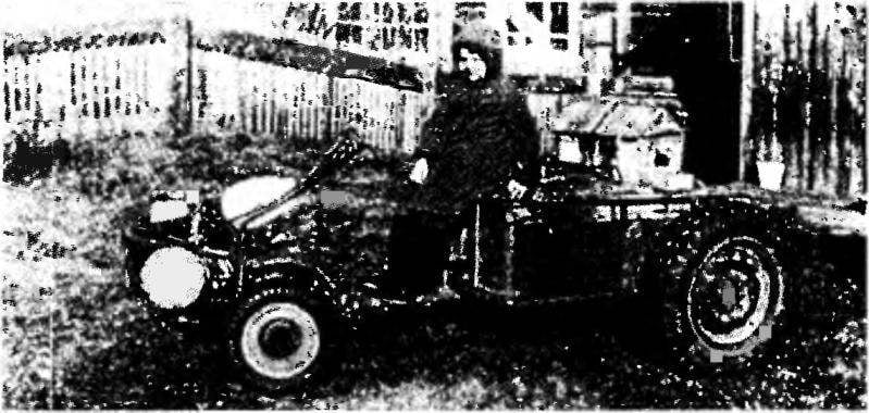
To the two front uprights of the frame is welded tool box is a triangular shape from steel sheet of 1.5 mm thick (trunk), sides and the edges of which are reinforced “ridges” and the frame with a wire liner. The trunk lid is made of thick plywood, covered with foam and vinyl leather, and serves as the driver seat. Cover is fixed to the frame hinge by using riveted to its plywood base hinge; the hinge line is here — grab handle (in the rear wall of the trunk is carved the appropriate window).
 
The truck
Cargo truck:
 
1 — the case of the hinge Assembly; 2 – pole (pipe 43x43x5); 3 — step (corrugated steel sheet s5); 4 — frame (tube 43x26x5); 5 — trunk (seat conventionally not shown); 6 — Board (sheet s1,5); 7 — railing (pipe 21×1,5); 8 — (pipe 18×1,5, 8); 9 — the bottom (sheet s1 ,5); 10 — the case of the axle shaft (2 PCs.); 11 — Klondike (steel sheet s5, 6 PCs); 12 — liner flanging (wire 03); 13 — drawer, rear (steel sheet 1,5 s).
 
Swivel

 
Swivel:
 
1 — housing; 2 — bearing 180205Е (2 PCs); 3 — axis; 4 — pole truck; 5 — washer; 6 — nut M20x1,5; 7 — pin; 8 — spacer; 9 — plug hinge Assembly of the cultivator.
 
Seat and trunk

 
Seat and trunk:
 
1 — upholstery (imitation leather); 2 — foam; 3 — hinge hinge (2 PCs); 4 — base (plywood s12); 5 — Kant (aluminum profile); 6 — drawer trunk (sheet s1,5); 7 insert-the crinoline (wire Ø3); 8 — wall box, rear (sheet s1 ,5).

 
Round cross tube of the frame can be called a truck axle because the welded parts of its undercarriage assemblies. Case they have flanges for mounting the base disc brakes and a cavity for the axles bearings. Axle turned on a lathe at the same time with the hubs under the wheels of the car GAZ-69. In the buildings of the navigation nodes they are held from axial movement outward locking screws M8. Properly collected and covered with grease ciatim-201, the navigation nodes worked perfectly for many years.
 
In addition, the bogie axle (rear middle) is welded to the eye — ear of a steel strip with a thickness of 10 mm, to which you can attach light sled.
 
The truck is equipped with a hydraulic brake, which is actuated by a pedal located under the right foot of the driver and held in the inoperative position of the cylindrical return spring. A pedal arm pivotally connected to the rod of the main brake cylinder (GAZ-51) attached to the bracket pegs and pipes (GAZ-69) is connected to actuators, brake cylinders (also from GAZ-69).
 
Running node
 
Running node:
 
1 — axle shaft; 2 — bearing 206 (2); 3 — oil seal (felt ring); 4 — the case of the semiaxis; 5 — spacer; 6 — a stopper (screw M8, 2); 7 — ring, spring, thrust; 8 — axle truck (tube 49×4,5); 9 — frame truck.
 
The location of the brake pedal

 
The location of the brake pedal:
 
1 — axis; 2 — step; 3 — pedal; 4 — shock absorber (rubber ring); 5 — shaft of the trolley; 6 return spring; 7 — the lever of a pedal; 8 —mounting bracket brake master cylinder.
 
Device hydraulic brake actuator

 
The device is a hydraulic brake actuator:
 
1 — the brake pedal; 2 — brake cylinder, main; 3 — fitting mounting;4 — pipeline; 5 — tee; 6 — clip (stripe 60×14, s2);7 —bushing rubber.

 
Such a serious brake system the truck was equipped after it turned out that the downhill engine braking is ineffective, especially when Laden truck, which tries to expand the tillers. And as rod with knobs relatively short, to steer could be hard. After installing the brakes this problem has disappeared.
 
Practice suggested other ways to improve the performance of walking tractor and truck. For example, I changed the design of the rotary unit of the drawbar, adding to its hinge, which naturally improved the grip of the wheels with the road surface, and the cultivator ceased to “porpoise”. Next, moved the truck axle closer to the middle of the body that unloaded swivel, reduced stress on the handlebar and a more rational distribution of weight on axes of two-wheel tractor and truck. The result of all these improvements reflected on the attached drawings.
 
Vladimir PETROV, c. Fish, Krasnoyarsk Krai

Recommend to read

  • LOOP-THE PUNCHLOOP-THE PUNCH
    Once I wheel the bike needed two washers. The same hand was not, and I decided to make them their own, as the piercer used an old door hinge. In one of her cards with a hacksaw sawed...
  • REMOTE CONTROL SYSTEMREMOTE CONTROL SYSTEM
    The proposed remote control system (remote control) is executed in the form of attachment to the radio commercial production. It allows you to control ten different loads with up to...