WALK-BEHIND WHEEL

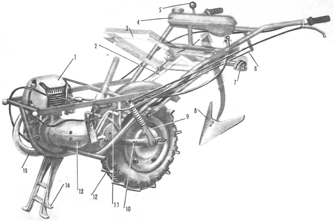
WALK-BEHIND WHEELFor simplicity, I decided to make the walk-behind, in-parzych, unicycle, and secondly, on the basis of units, components and parts of various machines manufactured in the factory. Took the frame of the motorcycle M-105. To do this, cut it up the pipe in four places: 60 mm higher than the front bracket of the engine mount 165 mm above the same rear bracket and 50 mm above the curved pipe going to the back of the pendulum fork (both sides).

The footboard of the frame cut off did not, as in case of accidental fall of tillers ka side they protect the engine and its components from damage. Moreover, it is possible to pivotally attach the thrust elements of the dozer blade.
 
Cropped so the pipe frame I modified is: the front tapered and welded to it the cross member from a half-inch steel pipe with a length of 340 mm, and in the rear put turned on a lathe axle (the joint provari), which serves as the axis of coupling with the two-wheeled freight Dolly.
 
Below the axle was welded I-beam shock absorbers with a length of 340 mm. Beam has lugs attaching the upper heads of the absorbers from the moped “Riga-12”.
To shortened the pipes going to the rear fork pendulum, with clutch welded arm control tillers and connected them between the rear crossmember and strut. The latter is attached to the tank from a moped “Riga-11”.
 
From the bottom to the strut welded two ears with holes for the remote gear lever (rod d 10 mm). To the right the lever put a plastic ball on the left — the initial rocking of the strip steel section 20X5 mm with hole for rod (rod d 8 mm). Secondary rocking of the shift lever on the gearbox and the engine.
 
Fig. 1. The dimensions of the tillers.
 
Fig. 1. Dimensions walk-behind.
 
Fig. 2. The frame design
 
Fig. 2. Frame design:
 
1 — the frame of the motorcycle M-105, 2 — mounting brackets motor, 3 — step, 4, 14 — mounting brackets of the pendulous fork, 5 — eyelet hanging equipment, 6 — pins fixing double comb, 7 — rear cross member with rack mounts fuel tank, 8 — spacer 9 — arm control, 10 — pin coupling with trolley, 11 — beam dampers, 12, 15 — reinforcements of the frame 13 is a horizontal connection, 16 front crossmember.

 
R and p. 3. The remote gear shift
 
R and S. 3. Remote shifter:
 
1 — control lever cultivator, 2 — bar, 3 — shift lever 4 — lug (2 PCs), 5 — primary rocking, 6 — thrust, 7 — secondary rocking chair (on the gearbox of the engine).

 
R and p. 4. Fan ring forced cooling
 
R and S. 4. The fan casing of forced cooling (the picture is simplified: the types of the left and right are shown only the front cheeks of the duct):
 
1 — intake, 2 — pipe, 3 — bolt MB, 4 — cheek duct.
 
R and p. 5. Beam absorbers.
 
R and S. 5. Beam absorbers.
 
Fig. 6. Revision of the pendulous fork
 
Fig. 6. Revision of circular plug (I — welding II — after welding):
 
1 — clutch (2 PCs), 2 — clip.

 
Front crossmember, beam absorbers, and control arms connected on both sides with horizontal connections — steel strips section mm 20X5, which make the design of the frame tillers hard.
 
Pendulum rear fork of the motorcycle M-105 I modified: expanded and shortened, so as the leading used front wheel with brake scooter “Electron”. The plug from the brake disc (front oblong hole) welded the bracket; it keeps the disc pads from twisting under braking.
Mud flap made from szczytna the rear wheels of the motorcycle M-105. In place of the passage of the chain force transfer plate further trimmed to the chain did not touch him. In front it is attached to the frame, and on the sides of the two tubes to the trunk road bike to the eyelets of mounting the equipment on the handles control of the cultivator.
 
Into eyes screwed special shaped bolts, which hooks frame hanging equipment held spring-loaded locks from a steel angle 30X30 mm.
 
Fig. 7. Shaped bolt.

 
R and p. 8. The impeller of the fan.
 
R and p. 8. The fan impeller.
 
R and p. 9. Bolt magneto and fan.
 
R and p. 9. Bolt magneto and fan.
 
Fig. 10. Cover air intake.
 
Fig. 10. Cover the air intake.
 
Fig. 11. Blank (I) driving sprocket and its manufacturer (II).
 
Fig. 11. Blank (I) driving sprocket and its manufacturer (II).
 
Fig. 12. Bearing bushing, driven sprocket.
 
Fig. 12. Bearing bushing, driven sprocket.
 
Fig. 13. Hairpin of fastening the sprocket to the wheel.
 
Fig. 13. Hairpin of fastening the sprocket to the wheel.
 
To controls, approximately 340 mm from the lugs, welded pins and bolts are M10 X 1.5 for dual-comb frame.
 
The engine of the motorcycle M-105. That it does not overheat during operation, right side mounted forced fan cooling — blowout of the cylinder head, which for convenience turned counterclockwise by 90 °. The impeller made of sheet aluminum having a thickness of 1.2 mm, and the cover of roofing iron with a thickness of 0,8 mm. For mounting on the same axis with magneto used a long threaded bolt M7 end, an elongated bushing and spring washer.
 
Fan housing is modular, it consists of air duct and air intake. The latter has a removable cover with holes, which is attached to the housing with one bolt M6 (bottom). The top cover has a two small corners of the rectangular cutout, it is held by them under the wall of the casing.
 
The duct and the air intake connected by two M6 bolts that are inserted the lugs are bent from both sides of the casing.
 
The cover attaches in three places: to the front engine bracket to the crankcase and to the right horizontal links.
 
Lever of kick starter was taken from a motorcycle M-105. For ease of launching it is slightly arched outwards. Air cleaner to carburetor barrels like motorcycle M-103. Exhaust pipe with nut and silencer of the motorcycle K-55. The muffler is attached with a M8 bolt to the lug welded to the frame of the cultivator.
 
Sprocket motor — homemade. She has 10 teeth and is designed for chain with a pitch of 19,05 mm. a Blank for it I machined on a lathe, and the bore d 12 mm under the teeth made on the drilling. Teeth to the desired configuration brought first, a metal saw, then a file. The splines in the center hole sawed a square needle file. Ready star tempered: heated in the flame of a gas burner, and then cooled in water.
The motive force from the engine is transmitted to the driven chain sprocket wheel with 54 teeth, taken from straw walkers of the combine harvester. Shaft sprocket is removed, the resulting hole in the pressed on sleeve, inner diameter which corresponds to the outer diameter of the housing at the oil seal wheel bearing scooter “Electron”. This sleeve is necessary to sprocket during operation is not shifted away from the wheel.
 
The asterisk is attached to the three wheel studs, machined from hexagon bar, under nuts spring washers supplied.
 
To on the chain did not get land and it is less worn, it is possible to make the protective cover, attaching it to the back of the pendulum fork.
 
For the best coupling of wheels with the ground I hooked it to the old chain with a pitch of 19,05 mm from the combine. To the chain every three levels (between) welded lugs of the steel strip 30X4 mm section of chain To avoid slipping, four grantsearch both sides of the welded side stops, curved on the tire of the wheel. If necessary, the chain can be easily removed by unscrewing the nuts of the through bolts.
 
Fuel from the tank to the carburetor is fed by gravity through a long hose. The throttle lever of the motorcycle M-105 is located on the right control arm tillers, the left clutch levers and decompressor from motorcycles “Voskhod” and To-55. Immediately rubber manual from “Java-350”.
 
Interchangeable agricultural implement for tillage mounted on the cultivator with the help of a special frame. When making it I used 1/2″, 3/4″ and 1″; tubes, strips section 30X5 and 50×6 mm, angle 40X40X4 mm, rod ø 10 mm pipe ø 13X10 mm from the trunk road bike. Brackets mounting additional guns taken from the old tractor cultivator (see picture). Make them your own is difficult, for making you can use the variant represented in the drawing (Fig. 17).
 
When processing land horse plow or Hiller-cultivator is better to install in the Central slot of the frame, and a plough with a tractor blade or Coulter — in the side slot.
 
Agricultural implement in the nests recorded thrust bolts M10, which is screwed into a threaded hole in the rear wall with nuts gain. Resistant bolts perform well, you don’t even have to use the locknuts.
 
Fig. 14. Sprocket driven.
 
Fig. 15. Frame mounted guns
 
Fig. 15. Frame attachments:
 
1 — double comb, 2, 3 — spring, 4 — axis comb, 5 — brackets mounting additional equipment, 6 — body frame, 7 — selhozgodu.

 
Fig. 16. Housing framework
 
Fig. 16. Body frame:
 
1 — hooks batches, 2 — hole for springs, 3 — rod, 4 — loop axis dual combs, 5 — supporting tube, 6 — area 40X40X4 mm, 7 — hole fixing bracket mounting additional equipment, 8 — Central socket, 9 — side socket 10 nut M10

 
Fig. 17. The headstock for more agricultural tools (improvised version).
 
Fig. 17. The headstock for more agricultural tools (improvised version).
 
Fig. 18. The potato digger
 
Fig. 18. Potato digger:
 
1 — fry 2 — field strap, 3 — tip (trimmed paw cultivator), 4 — teeth.

 
Selhozgodu you can quickly raise, lower or change with frame, because it is quick. To unhook, just a few seconds. This spring loaded bars pulled forward, the hooks of the frame immediately jumps to shaped bolts and remove the double comb with pins.
 
Internal dimensions of the sockets of the frame (46X17 mm) is designed for bipod serial tractor cultivators. Shield charged with a horse plough, is also mounted on a bipod, partly cropped at the bottom and provided with bolt holes pemea. This plow cultivator plow to a depth of 200 mm. One cultivator with a paw width of 330 mm works the soil to a depth of 250 mm, an equestrian well-Hiller to hill the potatoes with row-spacing width of 500-600 mm.
 
From the clutches of the cultivator, old garden fork and steel strip section 50X6 300 mm in length I made a potato. To the riser welded the strip at an angle of 5° to the horizon — bar field. On the front it has the shape of a wedge. The left wing of the paws trimmed so that it overlaps the field level. From the garden fork a triangular file has three teeth sawed off and welded to the right-wing legs on the inside. The lower ends of the teeth were ground off after welding under a corner 45° to reduce the resistance of the soil.
 
This digger is inserted into the left slot of the frame, the potatoes they dug from a depth of about 150-200 mm.
 
E. FEOFILAKTOV, p. N e m a, Kirov region.

Recommend to read

  • LUCKY THE DRAGONFLYLUCKY THE DRAGONFLY
    The first USSR championship flying micro models. It was held in 1990 at the Palace of sports "Dynamo" (room category III, altitude up to 30 m), but due to the lack of advertising and...
  • MOMENTUM BELIEVES ELECTRONICSMOMENTUM BELIEVES ELECTRONICS
    Ubiquitous electronics is steadily expanding its "activities". Where yesterday it was considered "foreign", today it becomes indispensable helper. Approval this fully applies to karting....