Can now be taken for the finalization of the Microdrive. Let’s start with the back cover carrying the slide and the carburettor nodes. First of all, carefully inspect the details of the carburetor. In most motors overlay threaded sits on its place with the “unthinkable” gap. To eliminate it, giving the output a tapered bore, futorki steel ball Ø 8-10 mm from the old ball and gently hitting it with a light hammer. The main thing is not to overdo it. Better gradually strengthen the strike as long as the overlay threaded fitting will not be included in the wall with a slight interference fit. This will eliminate fuel leaks out of the spray holes is associated with the instability of the regime of work and a bad run.
Industrial compression Microdrive MARZ working volume of 2.5 cm3 :
1 — screw kontrpartiya, 2 — cylinder, 3 — controlling, 4 — sleeve, 5 — M3 screw, 6 — pin plunger, 7 — main bearing, 8 — rear bearing 9 — bearing washer, 10 — cone, 11 Kok, 12 — crankshaft, 13 — Carter, 14 — connecting rod, 15 — valve, 16 — gasket, 17 — cover 18 — screw M2,5, 19 — o-ring, 20 — overlay threaded, 21 — clamping sleeves, 22 — spacer sleeve 23 a piston, 24 is a nozzle 25 — nut 26 — nut, a 27 — needle.
Looks around the nozzle, if necessary, the needle was corrected, and undermined: Sirima seats, clearly visible on the cone of the needle must be the same around the entire circumference of the needle, wrapped the position of the jet unacceptable even the slightest leakage.
A factor that largely affect the operation and running of the engine, is the inaccuracy of the landing of the jet on the tide wall. As a rule, planting the ends of the tide either not treated or treated roughly. This causes air leak in the carb. Of course, air to pass through narrow passages much easier than to suck a fairly viscous fuel — hence the inability to start the motor to bring the regime and especially to achieve stable operation by the model with the constantly changing external conditions.
Sealing the nozzle fails prebilovci wall and located under the nut and the flange of the housing of the nozzle elastic plastic washers.
It is now up to test crankshaft and install it in the crankcase. To start with all the corners removed, and burrs from the crank cheek gently cleaned off the mill scale. Many people forget that this scale often brings much more harm than has been accidentally left in the crankcase the metal shavings! During execution of work the root ball should be securely covered against the ingress of any particles of a dense cloth.
Again wash the shaft with bearing and checking the ease of rotation, to control the put the node into the crankcase. Most engines are not secured with the seal of the crankcase near the crankshaft. To check this the easiest by trying to suck air through the toe of the crankcase when assembled the shaft and both bearings (in the absolutely dry state). If the tightness is no need to reproduce a seal, applied on the Microdrive MK-12V. Right behind main journal is paronitovye, cardboard (best from presspan or cardboard), nylon, or PTFE washer with a thickness of about 0.5 — 0.6 mm. In a pinch you can use a set of three washers cut from thick drawing paper. To achieve accurate size and shape is possible, cutting of sheet material parts using the “gregoratos” (tight compass gripped in the spring chip hard razor blades), and initially formed the outer circle, and only then, with the same center. It is better to use a tenth, but the right washer than the first, at least slightly inaccurate. The crankshaft must be in the washer with little effort. It’s a little difficult the first test run, but after running and running reliable seal is ensured for a long time. The mounting shaft ends with the sealing of the crankshaft bearing in the crankcase epoxy resin. To avoid this operation, unfortunately, does not — first shift the outer bearing race in the crankcase leads to the development of the landing surface, the loss of precision of the mutual position of the axis of the cylinder and the shaft depressurizing the sock Carter. The result will be a clear deterioration of the characteristics of a “couple” because of introduced in steel and cast iron particles of aluminum. Gluing is conducted on a rigid epoxy resin, possible additive in clay bronze powder from the kit paint “under the gold”. The resin is applied in small quantities on degreased with acetone the surface, after mounting of the node surpluses (in good sealing they should not be) removed with acetone soaked cotton wool. It should be noted that the installation of crankshaft bearing resin makes sense only before the first start. Postponed “for later” — and glue the knot definitely will not succeed.
After complete curing of the resin (after two days) crankcase set cylinder liner with piston and connecting rod mounted on the cylinder head, the friction parts are lubricated by the liquid lubricating oil. Controlling and air screw also needed for responsible checking control stability of the connecting rod on the crank. A wall with a spool not mounted to monitor the parts during propertyvalue of the crankshaft. It should rotate slowly and then quickly, simulating start-up, pressing and pursing controlling. If you are lucky and got a good engine, the connecting rod is in any case will sit flush against the cheek of the crank. When it Zdzvizhkou from cheek trying to turn the piston (often the pin hole reamed in it is inaccurate and due to a reshuffle to get rid of the sliding rod). If this does not work, then a hole in the piston is made quite accurately and the upper head of the connecting rod will last long. The required position of the rod will provide pripravka landing end of the crankcase under the sleeve. After complete removal of the protruding sections of the tides of the crankcase under the screws need a little (0.1—0.2 mm) to cut the back of the landing ledge, proshlifovat end on the glass with fine abrasive powder (you can get it by rubbing skin on skin) and again after collecting the motor to control the operation of the connecting rod. If necessary, the operation is repeated.
What does it do? As the test showed, from the proper position of the connecting rod almost primarily depend on resource capacity and mode of operation of the motor. Due to Vicosa the axis of the cylinder ago managed to save the “bad” engines, which did not respond to any other methods of improvements.
So, having achieved the desired, you can run the motor? No, sorry, not yet. But not for much longer: check the clearance (backlash) of the axial stroke of the spool and shorten the sump for the rear end. The objective can be considered achieved if the backlash does not exceed 0.3 mm, and the measurements need to clean off the mill scale from the spool and sanded his face with a fine emery paper. In the extreme case, lead the shank of the crank is put on a steel washer with an inner Ø 2.5 mm, to prevent the rod from accidentally slipping back and then running in an unplanned situation, and from the roughing of the connecting rod rough surface of the cheeks of the spool.
So, unfortunately, you need to prepare any material excavated from the engine packaging for the first run. Only after you have done all of the recommended operation, the motor can be run, to establish the model and make it several times to fly, sail or drive. Well, about how to give the engine a chance to work in his entire, albeit small, effect as to provide some resource — we’ll talk about that next time.
V. TIKHOMIROV, master of sports of the USSR in aircraft modeling
Recommend to read ELECTRONIC MANOMETER On the instructions of the enterprises of Dzerzhinsk-khimpromenergo in the design office of the school # 2 of Dzerzhinsk, Gorky region, the guys have designed and built a device for... THEN JUST A WARDROBE, A TABLE WITH WARDROBE In our small apartment and the kitchen is small: only 6 m2. Not really much to go, but there is also a need in the dining table because the kitchen in our conditions, multifunction room,... 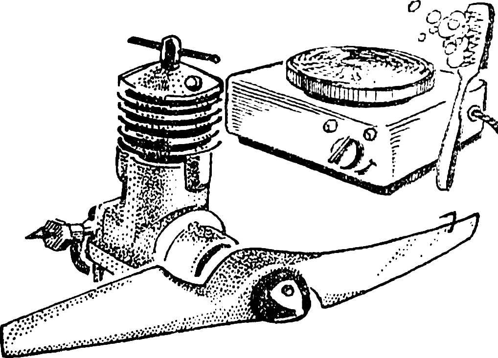
 On the shelves of the “Young technician” to replace the outdated MK-12V has received a new domestic micro-DISTRICT is 2.5. However, unfortunately, the present mass model was not too successful. The DISTRICT bears no comparison even produced a long time ago “twelfth” with the barrel red jacket.