Cord high-speed airboat engine 2.5 cm3 and propeller:
1 — shaft bracket propeller, 2 — cone, u-joint, 3 — propeller shaft 4 — two-part damping system exhaust (resonance), 5 — cowl muffler, 6 — housing, 7 — fore float, an 8 — beam 9 — front eyelet hitch “bridle”, 10 — window, fence cooling air 11 — CSTOM KRAS engine working volume of 2.5 cm3 , 12 — wing 13 — back ear sample “bridle”, 14 — flip cover-fairing power plant.
The comparison of speeds is obtained when installed on a sloped steps model and conventional, direct, revealed — new profitable and on calm water. While usual floats athletes have to choose simultaneously multiple parameters (the width of the sole, the corners of the “attack” rednich surfaces, alignment of the whole model, affecting the load distribution on the stern and bow pieces), ensuring minimal drag losses, but now the task is largely simplified due to the effect of self-alignment load-bearing properties of the “keeled” bow. Increased load on floats or decreased speed then the nose of the model is slightly lowered, and the work will include additional surface rednich soles. Is the airboat to reach the regime — and the floats will touch the water with only the corners, reducing the loss to overcome the hydrodynamic resistance to a minimum.
The introduction of deadrise gave the opportunity to obtain and excellent starting characteristics, which are of paramount importance for devices of young athletes. Start conditions are improving due to the trend of high-speed care from the circle at startup. Yet the model has not picked up speed and the position of roll is not stabilized by the tension of the cords, it is due to the effect of the reactive torque tends to tilt to the right. Thus, the right float at the start is more loaded and the hydrodynamic force on its beveled sole takes his nose out of the circle. As a result, to run a model a lot easier.
Another innovation provides stabilization mode semi-submerged propeller. In the struggle for higher speed the problem of optimization of the propeller is generally one of the most important. Moreover, the task is very difficult and ambiguous.
If the efficiency of engine boosting, we can see specific measurements on power balance booth, about the work of the propeller, only indirectly, by changes of speed in the race. The mode of propulsion is simultaneously affected by many interrelated factors. To study the isolated effect on traction and speed alone, abandoning the others, is simply impossible.
To facilitate the process of selection-rotor, we have tried to install on the rear of the hull wing. The angle adjustment fixing it is possible to achieve clamping of the stern to the water or, conversely, unloading of the propeller. Test launches showed that the impact of the aerodynamic vertical force (at a speed of about 150 km/h wing area of 1 DM2 can create a force of about 1 kgf) to the mode of propulsion is huge! Through the use of wing we were able to get good results even with screws, considered we in the circle failed.
Apparently, these thrusters at a satisfactory combination of diameter, pitch, shape and profile of the blades were in need of correction (and stabilization) depth of immersion. And with significant pushing out effect, characteristic of modern “polupogruzhnyh”, to influence the real value of their penetration could only be possible by changing the weight aft or the alignment of the whole model. As a rule, neither do not lead to satisfactory results immediately worsened many important characteristics of high-speed.
The aft part of the model:
1 — thruster, 2 — bracket, propeller shaft, 3 — boss, 4 — top covering the aft, 5 — bottom, 6 — window exhaust oil from the cavity of the fairing 7, the clamp securing the rear portion of the muffler, 8 — lug mounting clamp and hitch stabilizer, 9 — lower part of the channel of the exhaust pipe, 10 — fairing of the muffler, 11 — silencer 12 — “radany” frame, 13 — the main part of the bottom, 14 — deadwood, 15 — intermediate shaft, 16 additional frame, 17 — cone of the cardan propeller shaft, 18 — back ear sample “bridle”, 19 — fastening screws of the bracket 20 to the sidewall of the housing.
The nose part of the model:
1 — intermediate shaft 2 — deadwood 3 — side enclosure, 4 — lower part of the channel of the exhaust pipe, 5 — cowl muffler, 6 — jointed hinge, 7 — clamp resonant exhaust pipe, 8 — flip cover-fairing, 9 silicone tube connection between the engine and the exhaust pipe 10 to the engine CSTOM KRAS, 11 — sinking the attachment point of the engine 12 fuel tank capacity of 40 — 60 cm3 , 13 — site installation traverse, 14 — bow boss 15 — top covering the forward part 16 — the bottom of the case, 17 — lug mounts traverse, 18 — tube drainage tank, 19 — filler-chamber tank, 20 — sticks, the motor, 21 — driven part of the universal joint shaft 22 and the flywheel, 23 — frame, 24 — bolt clamp, 25 — front frame, 26 — silicone gasket.
We now consider the original solutions and on the nodes, requiring modelers the most attention.
As already mentioned, the case is accomplished by perekleivanie otfugovannyh plates in contrast to the traditional method of chiselling out of the bar. In addition to simplifying the manufacture, for re-housing characteristic increased strength with minimal weight and less prone to cracking under the influence of moisture and loads. In addition, the box details the set power and the intermediate frames are usually made in the form of bulkheads left by the gouging of the bar and therefore have the most unfavorable direction of the wood fibers. It should be noted and great accuracy of fitting load-bearing parts to each other, which ensures their secure hold in the rectangular case at minimal cost glue.
In the design of the case, special attention was paid to reducing noise. The rules stipulate permissible level, so any innovation that reduces the “vociferous” microglossia, will conduct a further boost engine that will ultimately increase the speed of córdoba.
Please note — fairing exhaust pipe is torqued to the rear of the hull. Thus it was possible to improve the streamlining of the model and substantially reduce its noise. In fact the resonance of the exhaust pipe is a great thin metal membrane, which transmits in the air a considerable sound energy from the exhaust gases of the engine. We “fenced off” the pipe from the surrounding atmosphere poltroncina fairing of plates of lime in the thickness 1,5—2 mm, pre-steamed and dried on a round mandrel. Low fairing exhaust pipe can be made of cardboard. After Assembly of the hull of the wooden elements and cardboard, impregnated with diluted liquid two-component parquet varnish.
The most noisy compartment model, of course, the motor. Usually it is closed by a fairing of the engine and is isolated from the surrounding space. However, the fairing has to do not only the intake of cooling air, but large Windows to manipulate with the starting belt. And each such window is a good “loophole” to noise. I will say, the transfer of fluctuations through these holes minor! And remember, what happens at occurrence of the slightest gap in the connection of the muffler with the exhaust pipe of the engine: immediately the impression that the system damping is completely absent.
The flywheel for the engine CSTOM KRAS.
Depreciation attachment engine:
1 — M3 screw, 2 — washer-cap, 3 — rubber washer-gasket, 4 — foot sump, 5 — threaded bushing with external thread M4X0,5 and inner M3.
Task maximum insulation engine compartment managed to solve in a simple way — cowl-fairing of the engine on our model’s flip! Now has no extra holes, and to operate, maintain and regulate the power system has become a lot easier. Immediately after zavodki the hood closes with a single motion, the latch automatically secures the fairing in this position.
Transfer case vibration from the operation of the motor is reduced and the application of the amortised mount Carter Motorama. If you use good ambulancewoman pairs and crank mechanism reset power elastically installed motor can not be afraid, especially with such a massive sump which has CSTOM KRAS of 2.5 cm3. Comparedata from the work of u-joint is jamming the mentioned “sealed” hood. To improve the efficiency of killing it accurately adjusted as to the body of the glider and the engine head.
We must dwell on common mistake many modelers on the shortcomings in the preparation of engine for running-in after re-opening. Most limited dismantling, inspection and flushing of the motor after Assembly it is immediately placed on the roller stand. But that’s about the scale, having high abrasive properties and a thick layer covering the cheek of the crankshaft, the entire surface of the inlet port and partially the surface of the liner in “black” performance “couples” are almost always forgotten. After starting the engine, some part peels off and instantly results in complete disrepair itself as “a couple”, and the main bearings of the crankshaft. Then wonder why quite a costly engine produces output of “Meteor”! To avoid this, the mill scale must be completely clean off sandpaper. For sure after this job you will be surprise the amount of abandoned plant in considered as ready engine “abrasive”. It is useful to see if there are any after polishing and lapping of casings subtle knife-like Burr at the edges of all Windows. In most cases the steel casings they are. And if you don’t want to cut the engine before the first seconds of his run, gently remove the burrs with bormashenko defined in it finger-like “stones”.
After execution of the works and washing parts checked for balancing of the motor has a significant influence on its maximum capacity, and the “noisiness” of the glider.
V. ILYASHENKO
Recommend to read THE SECOND “BREATH” BIRDS First image of indoor model airplanes made of bird feathers, I saw in the years of the great Patriotic war, even as a boy. Father was at the front, and my mother and my younger sister... WITH THE RUBBER MOTOR AND WITHOUT Schematic model of the airframe and the aircraft, as you know, started flying much earlier than their full-size prototypes. Paving the real aircraft's path in the sky, they are now... 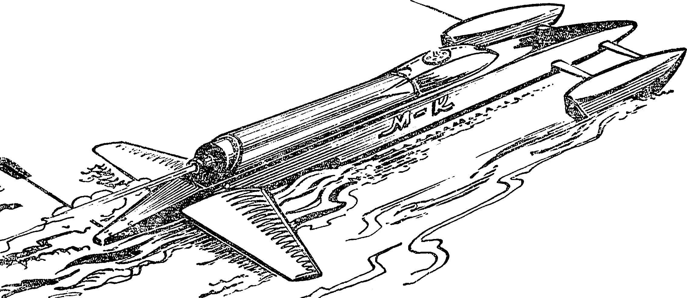
 Today our story is about the original high-speed input developed in the circle of children’s club “Iskatel”. Designed for the most advanced scheme, it contains a number of technical innovations that may be of interest to experienced athletes. Cord hydroplane class A1 favorably known development the lack of scarce or toxic in the materials — balsa, glass and carbon fiber reinforced plastics, which gives the possibility of recommending the model for the building even in the school clubs shipmodelbuilding. The use of standard domestic engine CSTOM KRAS ensures the implementation of fitness standards on the level of a first level up to the candidate master of sports.