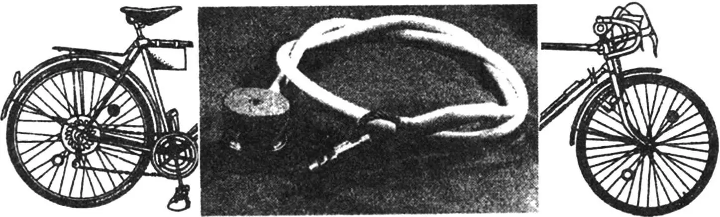
A small piece of steel cable, sheathed in a tubular plastic cover, enters a metal cylinder smaller than a hockey puck at its ends. This is a bicycle lock designed to prevent theft. It allows you to secure the bicycle to a post or something else, and in the absence of anything suitable—to lock the wheels from rotating.
The lock is keyless, combination-operated. One end of its cable can be released and locked again.
The lock mechanism is not complicated. Two end pieces are pressed onto the cable ends (the photo shows the initial version of cable termination). The right end piece is fixed with the ability to rotate in the housing, while the left one has a groove “п” for accommodating locking elements—the rims of the front and rear discs. In the locked position, the left end piece is inserted into a radial hole in the housing until it stops, and the disc rims are located in the end piece groove.
Both discs are fixed in the housing with retaining rings with the ability to rotate: they can occupy up to ten fixed positions, in one of which the cutout “в” in the disc rim coincides with the hole in the housing for the left end piece. This corresponds to the open position of the lock for that disc. The discs are rotated by the front drum, which, with the help of a shaft (when it is axially moved to extreme positions), alternately engages with both discs.
The interaction of the discs with the housing occurs like a ratchet, when under the action of a spring, balls jump over the depressions in the discs. By counting the clicks when rotating the front drum, engaged first with one, then with the other disc, the lock is brought to the open position. For a quarter turn, the ball rolls along the surface of the disc without depressions, creating a pause in the clicks. From this pause, the code count begins in one direction or the other.
The connection of the rear drum with the shaft allows their relative rotation; therefore, not being a driving element (it doesn’t even have knurling), the rear drum serves as a blocking cover, preventing code selection by feel when rotating the disc nearest to it. The cable is “hidden” in a heat-shrink tubing cover of suitable diameter for aesthetics.
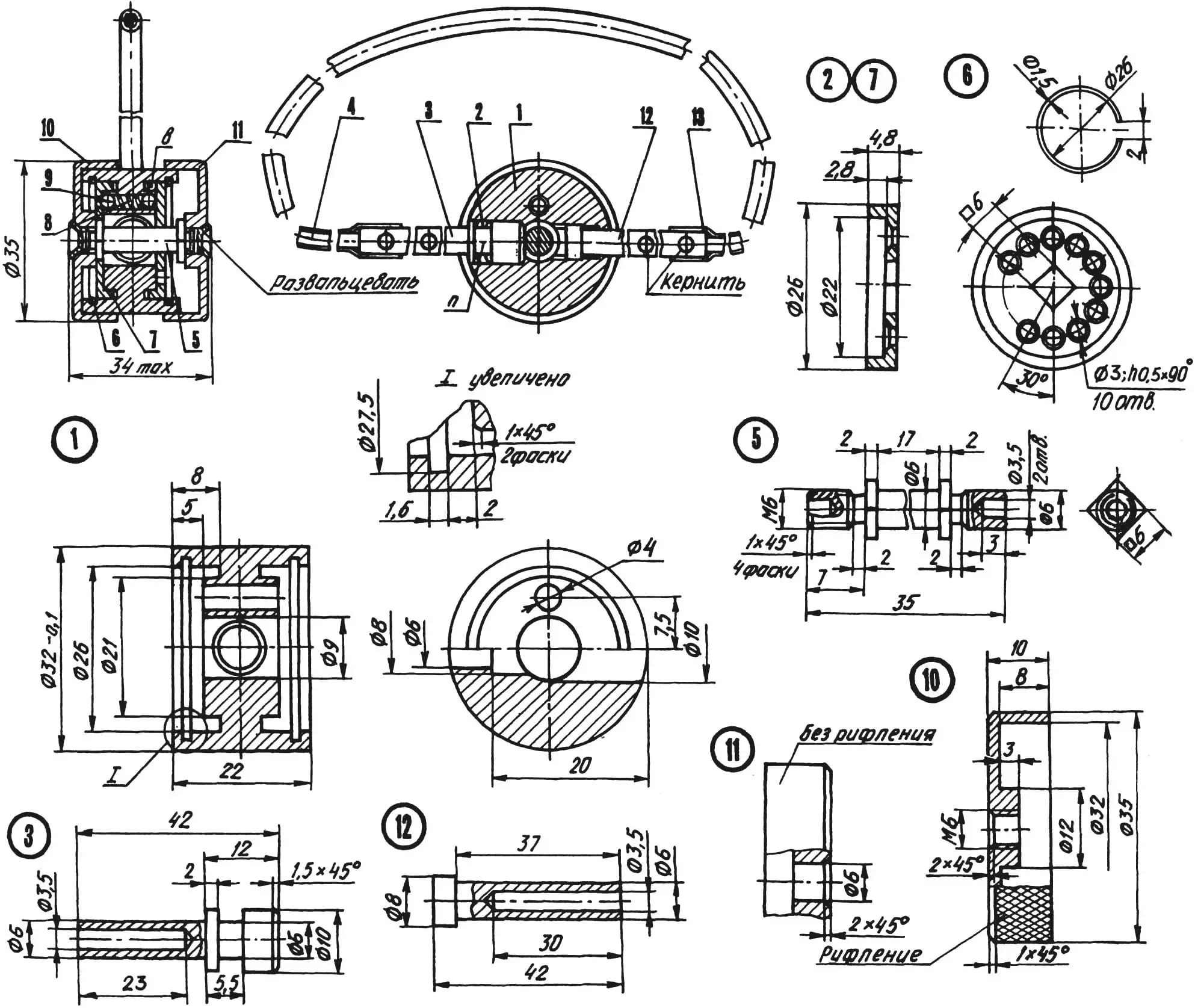
1 — housing; 2 — rear disc; 3 — left (lockable) end piece; 4 — cable (Ø3, L800); 5 — shaft; 6 — retaining ring (2 pcs.); 7 — front disc; 8 — spring; 9 — ball (2 pcs.); 10 — front drum; 11 — rear drum; 12 — right (fixed) end piece; 13 — cable cover (heat-shrink tubing)
The lock housing is made from duralumin, other machined parts—from steel 20.
For the discs, a certain manufacturing sequence is required, guaranteeing the lock’s precise operation. First, it is necessary to machine the end surface of the disc blank on a lathe, then drill a central hole with a diameter of 6 to a depth of 6 mm and perform a boring with a diameter of 22 to a depth of 2.8 mm. Next, machine the outer cylindrical surface of the disc with a diameter of 26 mm, using the housing as a gauge. The fit should be such that the housing rotates freely on the disc blank, but without radial play. Finally, cut the part to size 4.8 mm.
Subsequent operations on the disc are performed together with the lock housing. The disc blank is inserted into it and occupies the design position. Using the housing as a jig, it is necessary to drill a hole with a diameter of 3 mm in the disc. Next, turning the disc relative to the housing by 30° and using it as a jig, drill a blind technological hole with a diameter of 3 mm in the housing parallel to its axis (not shown in the drawings). Inserting a rod with a diameter of 3 mm into it, fix the angular displacement of the disc by another 30° and, again using the housing as a jig, drill a second hole with a diameter of 3 mm in the disc. Next, shifting the disc each time by one step, drill eight more holes so that there are 10 in total.
The final stage is countersinking the holes in the disc to a depth of 0.5 mm. Here, one must try to make all depressions identical.
The finished discs must be marked as front and rear and, when assembling the lock, installed only in their place (individual fitting).
It remains to file the central hole with a diameter of 6 mm in each disc into a square with a side of 6 mm, and ream the drawing hole with a diameter of 3 mm in the housing to 4 mm.
For marking the cutouts in the disc rims, insert balls with a diameter of 4 mm (suitable from bicycle pedal bearings) and a spring into the housing. Next, installing the discs and holding the entire assembly together with the thumb and index finger, achieve that each ball ends up in one of the depressions of its disc. The serial number of the depression is the code of that disc.
Through the hole in the housing with a diameter of 10 mm, it is necessary to mark the cutouts on the disc rims with a scriber. Disassemble the assembly and mill (or file) the cutouts, increasing their radius by 0.5 mm.
Retaining rings are made from steel wire with a diameter of 1.5—1.6 mm.
For the flexible “shackle” of the lock with a length of 800 mm, a piece of steel cable with a diameter of 3 mm is suitable (one strand from a thicker cable can be used).
Before final installation, the lock parts must be lubricated with a thin layer of grease to prevent corrosion.
The assembly sequence can be as follows. Insert the right end piece into the housing in its place, and the cable (to the stop) into the end piece tube, and peen it there with a center punch in three points.
Put heat-shrink tubing of the necessary length on the cable and the right end piece tube so that it allows peening the other end of the cable in the left end piece.
Assemble the ratchet, fixing the discs in the housing with retaining rings. Align the disc cutouts with the housing hole with a diameter of 10 mm. Check the “insertability” of the left end piece into the housing socket; if it doesn’t fit, then disassemble, fit the cutouts with a file, and reassemble.
When assembling the ratchet, it is better to add a pinch of graphite powder, because liquid or grease will affect the ratchet’s precision in cold weather (the lock will have to be warmed up for some time).
Thread the front drum onto the shaft. Insert the shaft into the housing and, engaging it alternately with both discs, check whether its square flanges pass freely into the corresponding holes in the discs in four possible engagement positions. If necessary, fit to a free, non-binding connection.
Remove the shaft and finally thread the front drum onto it to the stop (with interference) and carefully, so as not to bend anything, peen the threaded end.
Insert the shaft into the housing again (in the design position), put the rear drum on to the stop, and peen this end of the shaft.
Now you can determine the lock code, for which engage the front drum with one of the discs and rotate it until a pause in the clicks. Then continue rotating the disc, counting the clicks, until the cutout in the disc rim aligns with the hole for the left end piece in the housing. The number of clicks will be the code of that disc for that rotation direction. Do the same with the other disc.
To close the lock, it is necessary to bring the discs to the open position, insert the left end piece into the lock housing to the stop, and, holding it in this position, with a light axial force and simultaneous rotation, engage the front drum with one of the discs. Engagement is indicated by a jump-like “sinking” of the drum in the direction of the axial force by the thickness of the disc wall. Rotate the drum until a pause in the clicks. To increase security, rotate the second disc to a pause in the clicks as well, engaging the front drum with it by its axial displacement relative to the housing, but in the opposite direction. After this, set this drum to the neutral position (without engagement with the discs).
To open the lock, it is necessary, counting the clicks, to set both discs according to the code and bring the front drum to the neutral position.
I. YANKIN, Baikonur, Kazakhstan
Recommend to read
 “BOTTOMLESS” BARREL
In the country or the plot is always required to have a supply of water for domestic needs. Keep the tank in the shower or reservoir for watering the plants and filled to the required... AQUAPLANE? NO, SNOWPLANE
These sleds, perhaps, the most simple design, gather them literally in half an hour. For the manufacture of snegopada will need straight grained boards 30 mm thick (200X1200); two strips...
