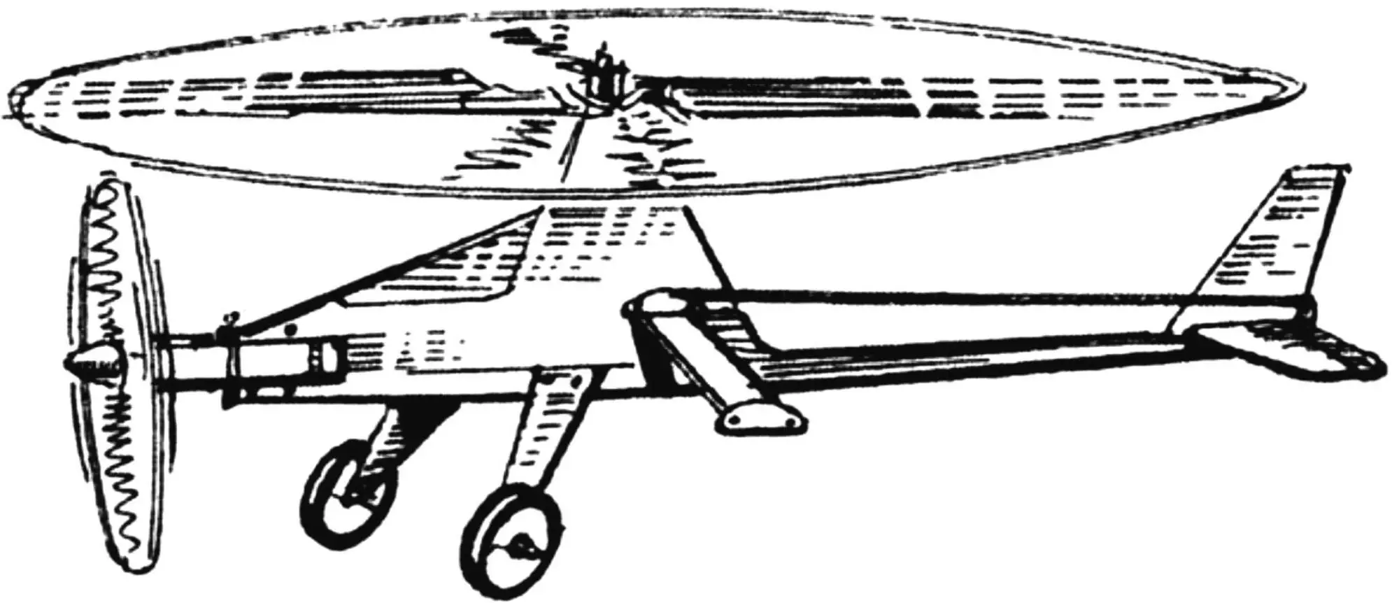
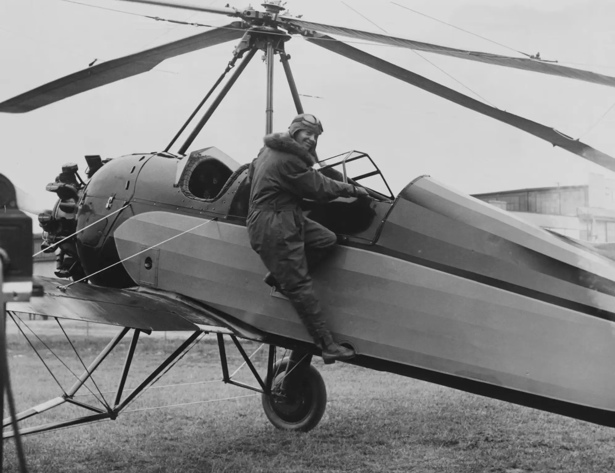
The term “autogyro” comes from two Greek words: autos — self, and gyros — rotation. In fact, they define the essence of this aircraft, in which lift is created by an airscrew-rotor that freely rotates under the action of the oncoming airflow, while forward motion is provided by a tractor or pusher propeller. The autogyro was invented by the Spanish aircraft designer Juan de la Cierva in 1919, and in 1922 he managed to create a machine with fairly good flight performance.
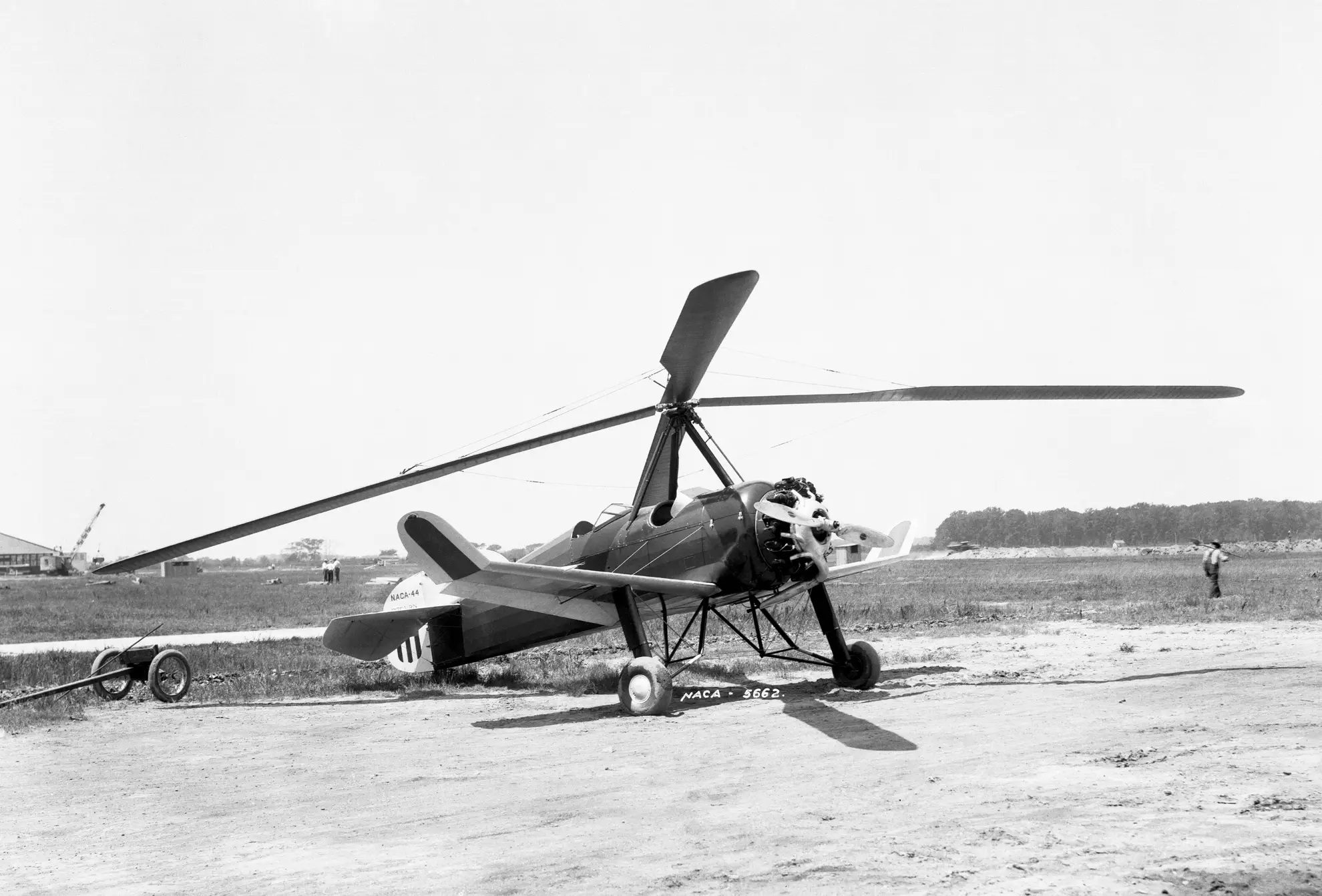
In our country, the first autogyro was built in 1929 by N. I. Kamov and N. K. Skrzhinsky. Up until the beginning of the Great Patriotic War, about a dozen and a half machines of various modifications were manufactured; one of them took part in combat as a reconnaissance and spotting aircraft. Today, autogyros remain only in amateur and sport aviation, and in a number of countries they are produced in series.
An autogyro model is a rotary-wing aircraft with a two-blade main rotor and a powerplant based on a compression-ignition engine with a displacement of 1.5 cc.
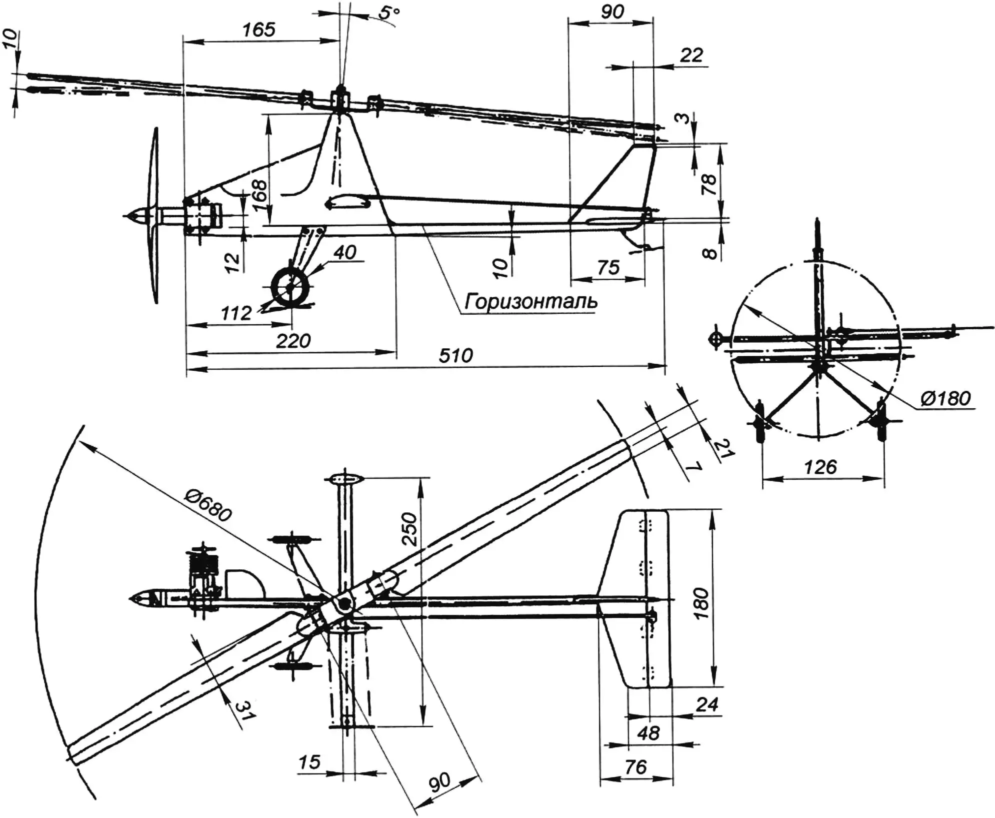
The fuselage is assembled from pine strips and covered with 1 mm plywood. Two horizontal strips serve as the engine mount; the rear part of the lower one is a boom on which the tail unit is mounted — a fin and a stabilizer with elevators. Perpendicular to the fuselage, along the rotor axis, a crosspiece glued with epoxy resin from five 1 mm plywood blanks is fixed with two bolts and nuts; the control bellcrank, a ballast weight of about 30 g, and a guide for the control lines are installed on it.
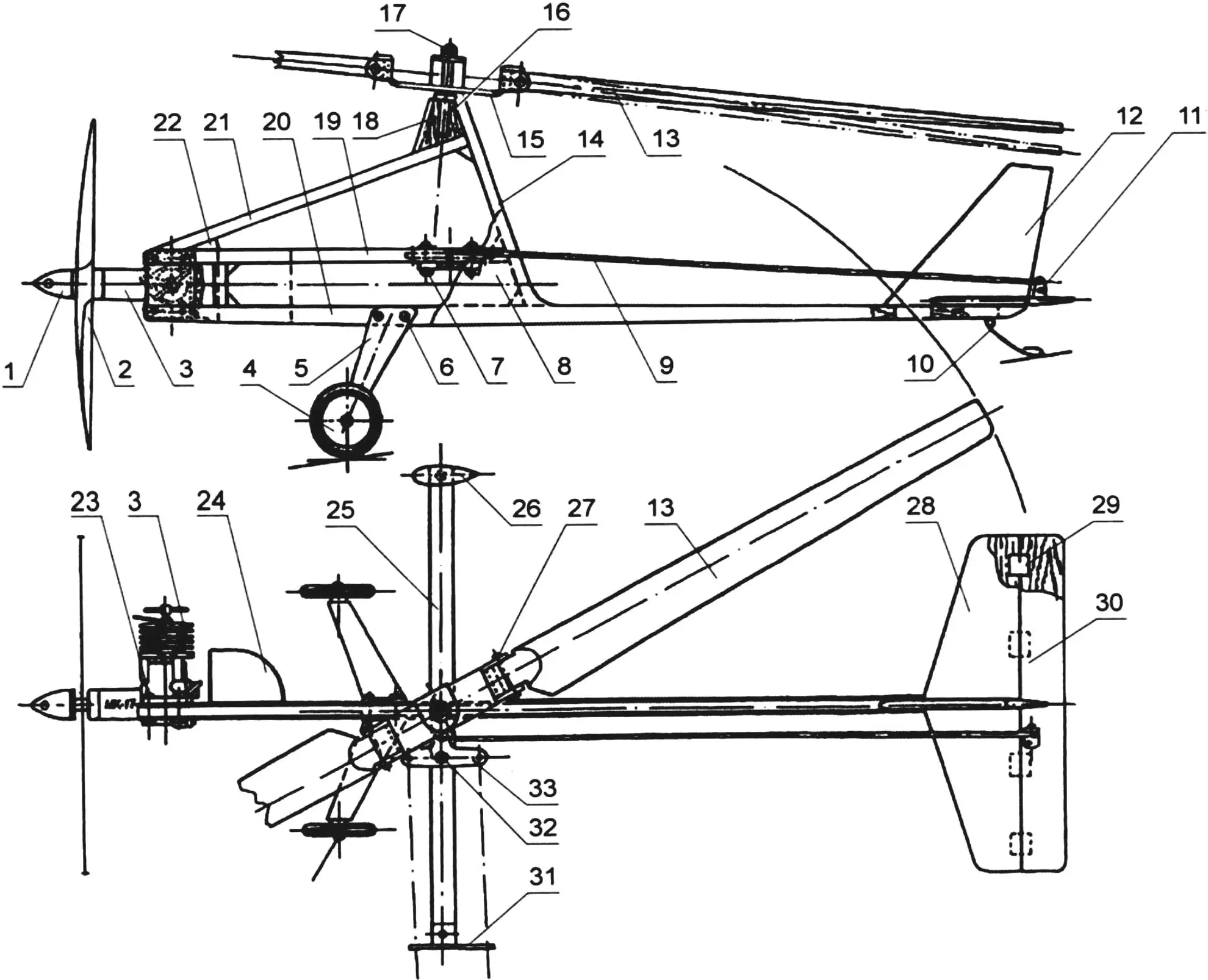
1 — propeller spinner; 2 — propeller; 3 — 1.5 cc engine; 4 — landing-gear wheel; 5 — landing-gear strut (duralumin s2.5 mm); 6 — landing-gear attachment (M3 bolt with nut); 7 — crosspiece attachment (M3 bolt with nut and washer); 8 — fuselage skin (plywood s1 mm); 9 — elevator control rod (duralumin spoke Ø2 mm); 10 — tail skid (OVS wire Ø2 mm); 11 — elevator control horn (duralumin s2 mm); 12 — fin (balsa s4 mm); 13 — main-rotor blade (linden 31×6 mm); 14 — rear pylon boom (pine 8×10 mm); 15 — main-rotor hub; 16 — hub axle; 17 — main-rotor axle (M3 stud with nut and washer); 18 — pylon boss; 19 — engine-mount boom (pine 10×8 mm); 20 — lower fuselage boom (pine 10×8 mm); 21 — forward fuselage boom (pine 8×10 mm); 22 — gusset (linden); 23 — engine attachment (M3 bolt with nut and washer); 24 — fuel tank (tinplate s0.3 mm); 25 — crosspiece (laminated from five layers of plywood s1 mm); 26 — ballast weight (lead 30 g); 27 — horizontal hinge pin of the main-rotor blade (steel Ø3 mm); 28 — horizontal stabilizer (balsa s4 mm); 29 — elevator hinge (nylon b10 mm); 30 — elevator (balsa s4 mm); 31 — control-line guide (duralumin s1 mm); 32 — control-bellcrank axle (M3 bolt with two nuts and two washers); 33 — control bellcrank
The tail unit is made entirely of balsa. The fin, stabilizer, and elevator are cut from 4 mm balsa sheets. The elevator is attached to the stabilizer on “soft” hinges made from strips of nylon tape about 10 mm wide. The control horn is made of duralumin and is mounted on the elevator with miniature self-tapping screws 2 mm in diameter.
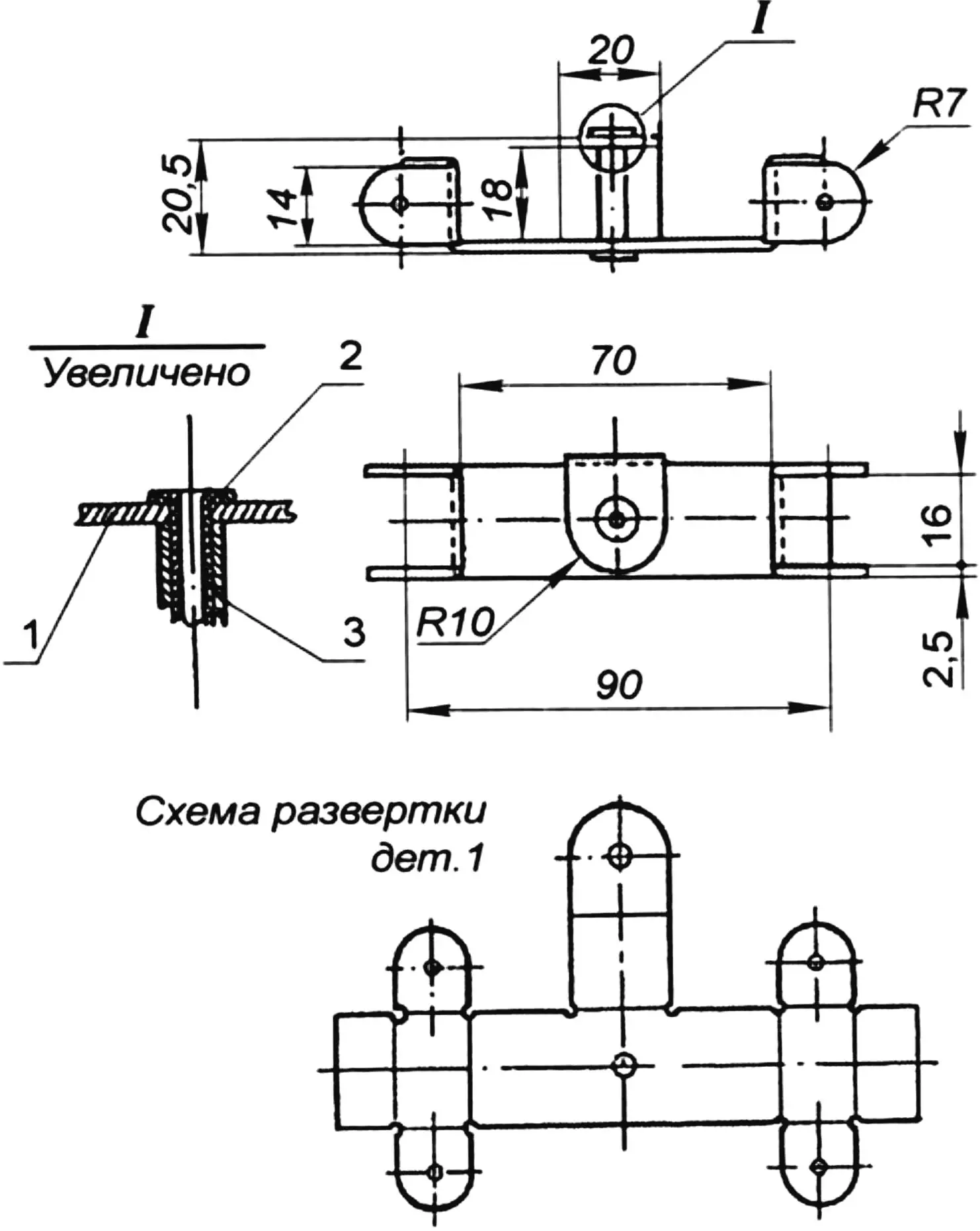
1 — body (duralumin s2.5 mm); 2 — sleeve (duralumin Ø5×0.5 mm); 3 — insert (gel-pen refill tube)
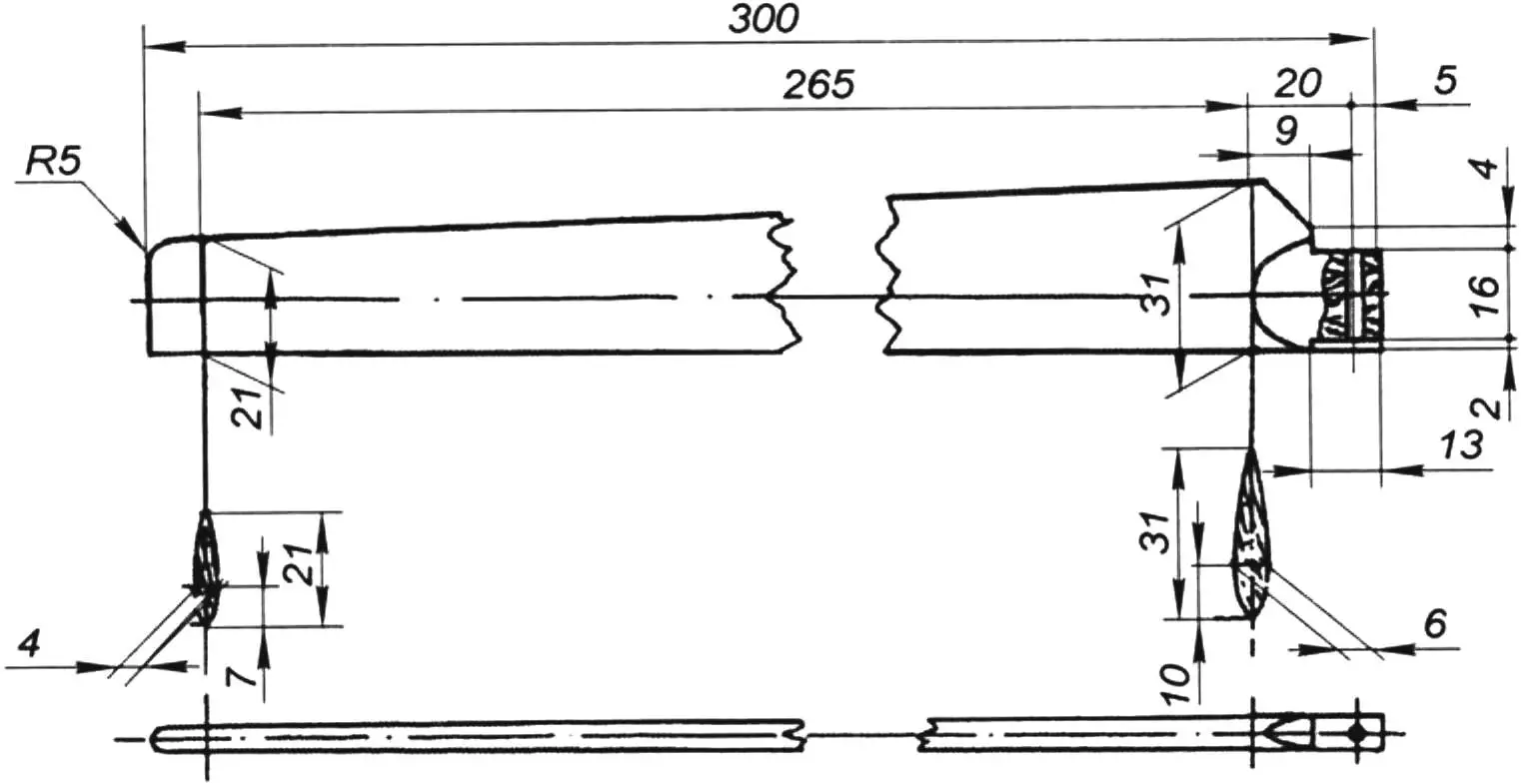
The main rotor is two-bladed. Each blade is fitted with a horizontal hinge that does not transmit to the model’s fuselage the overturning moment that arises when the blades are blown by the airflow. On the right, the blade moves into the oncoming flow; on the left, it moves with the flow. Accordingly, a difference in lift appears on the right and left sides of the aircraft, along with a moment that tends to overturn it. The blades, cut from linden strips, are essentially wings with a symmetrical airfoil of 20 percent relative thickness. The maximum blade thickness is located at 30 percent of the local chord from the leading edge. The main-rotor hub is cut and bent from 2.5 mm sheet duralumin. The blank for it is laid out according to the development drawing with a small allowance; final machining of the part and drilling of the holes are done after the blank is bent. The hub hinge consists of a length of duralumin tubing with an inside diameter of about 4 mm and an insert cut from a ballpoint-pen refill. The insert is secured with a metal mandrel heated to the softening temperature of the refill. The pitch of the main rotor is adjusted by twisting the horizontal part of the hub — this can be done with two pairs of round-nose pliers. The hub axle is made from a steel stud with an M3 thread, glued into a linden pylon in the upper part of the fuselage.
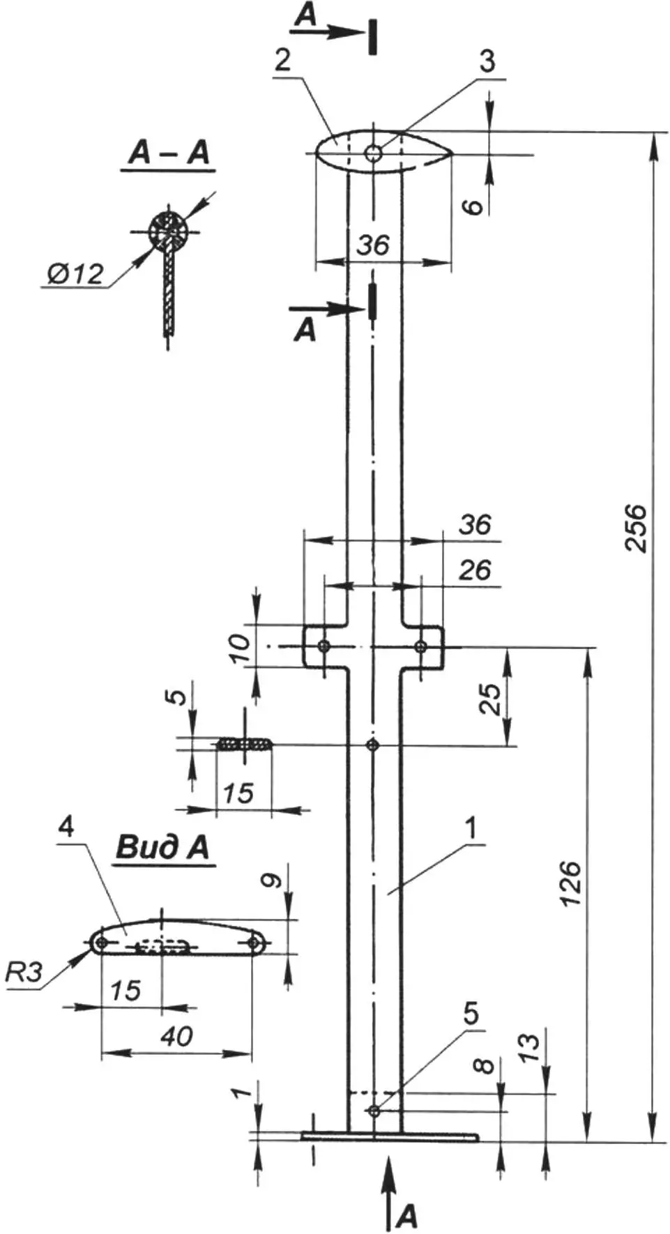
1 — crosspiece base (laminated from five layers of plywood s1 mm); 2 — ballast weight (lead 30 g); 3 — rivet (lead); 4 — control-line guide (duralumin s1 mm); 5 — guide attachment (rivet, aluminum wire Ø2 mm)
The model’s landing gear is of the spring type; its struts are cut from 2.5 mm sheet duralumin and fastened to the fuselage with a pair of bolts and nuts. The 40 mm diameter wheels are plastic ones from a suitable children’s toy.
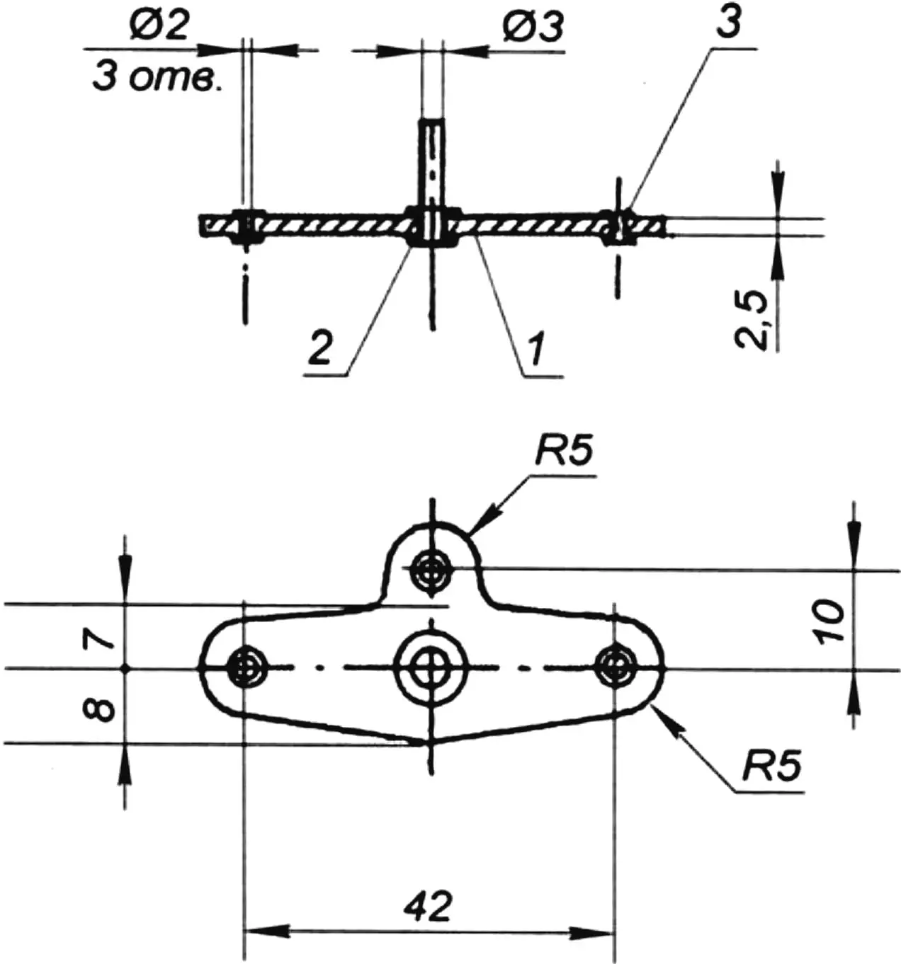
1 — bellcrank (duralumin s2.5 mm); 2 — large bushing (part of a gel-pen refill); 3 — small bushing (part of a ballpoint-pen refill)
The fuel tank is soldered from 0.3 mm tinplate. The feed tube, as well as the filler and vent tubes, are copper. The tank is attached to the fuselage with two self-tapping screws.
The finish of the model is quite ordinary: sanding and painting with enamels of suitable colors.
Autogyro flights are performed on control lines 10–12 m long. After warming up the engine, it is recommended to spin up the rotor and only then lift the aircraft into the air. Also note that the power of a 1.5 cc motor is not enough for advanced aerobatics — this is an entry-level model. After mastering takeoff, level flight, and landing, it makes sense to fit the model with a more powerful engine of up to 2.5 cc displacement.
“Modelist-Konstruktor” No. 9’2025, Igor SOROKIN
Recommend to read
 THE STOOL UNDER THE PHONE
Have a shelf or drawer under the phone, of course, good. However, if the conversation is delayed, the easier it would be to continue his browsing. This opportunity is provided by... MORE ABOUT THE MINI-FARM
"In the journal "modelist-Konstruktor" No. 5 in 1983 we were interested rabbit mini farm inventor I. N. Mikhailov: immediately appreciated the amenities which are incorporated in this...
