Winter kordovye velocity model snowmobiles are building in our country, thousands of students avtomodelistov. The interest has Particularly increased in recent Years. It seems that on the ice kartodromo original sports equipment in which it is difficult to know clumsy chetyrehlistnyj snowmobile the recent past.
In our group there were several models. However, the original design had considerably refined, because our snowmobiles were intended specifically for beginners. First of all, remade the engine mount under polutorametrovy Microdrive MK-17, which replaced the “Rhythm”. Most, we think, an interesting element of our model has become a kind of autopilot, not allowing the sleigh to fly in the air. With it we also managed to eliminate the threat from swinging the nose to the tail and to provide a strictly horizontal position the speed on the course.
We offer you to make this model. Hope you will help our design and technological recommendations.
The case of the model of two fake bars. Suggest to combine semi-finished parts 6 and 12 (see figure) polyvinyl acetate glue using a paper strip (e.g., from Whatman) and then process and shared by the outer circuit. Immediately to obtain the necessary alignment of the connection screws, drilled holes ø 10 and 16 mm. Next, the blanks are separated with a sharp knife and hollows out a cavity of the housing.
Racing control line model snowmobiles :
1 — spinner (steel), 2 — puck-deflector (steel) 3 — propeller 170 X 170 mm, 4 — Microdrive MK-17, 5 — fuel tank 6 — upper body (Linden), 7 — tail boom (duralumin D16T, T10 X 0.5 mm), 8 — skid (wire OVS d 1.5 mm), 9 — thrust (steel spokes d 1-1. 5 mm), 10 — horse, 11 — front wheel (duralumin D16T), 12 — the lower part of the body (Linden) 13 — stabilizer (lime), 14 — the wheel (Linden).
For engine installation prepare four threaded bushings of brass or copper tube with internal thread M3. Sleeve are stuck into the holes in the bottom of the hull.
Fuel tank solder made of tin. So it is tight and beautiful, it is advisable to work on the mandrel of beech or oak. Using it, first villotte two cheek-side, and then solder the sides. In the past have holes for the pipe supply, drainage and filling, and then gently solder the cheeks.
Fuel tank :
1 — shell (tin 0.3 mm thick), 2, 3 — sidewall (plate 0.3 mm thick), 4 — filling pipe (copper, brass T4 X 0.5 mm), 5 — the drain pipe (copper, brass T4 X 0.5 mm) 6 — supply pipe (copper, brass T4 X 0.5 mm).
The “legs” of the chassis is of sheet duralumin D16T, each attached to a corresponding foot of the engine. Racks teardrop-shaped cross-section.
Each horse is assembled from three metal plates, wherein the Central part is of bronze, better yet, titanium, and cheeks from any metal, for example aluminum. One of the cheeks of the left skate is cut out for-a lever controlling an automatic stabilizer of aeromodel.
The tail boom is of duralumin tube outer diameter of about 10 mm. In principle, it can be wood, but then its cross-section will have to increase.
The stabilizer and rudder is made of Linden planks. After finishing and painting the wheel pressurewhat to the stabilizer nylon thread. On the left side of it is an aluminium one. The stabilizer is fixed on the tail boom with epoxy glue.
Spinner composite: shaped nut and washer-cone. The material for these parts is chosen when balancing the model, however, in our experience, it is better to do steel.
The rod connecting the lever of the ridge and the hog steering stabilizer, we vygeboom of steel knitting needles d 1 — 1.5 mm. Fixing the PA thrust levers — soldering tin washers.
Cord strap is fixed on the left foot of the engine.
Left skate (the right runs without lever) :
1 — internal cheek (D16T),2 — sting of the skate (bronze, titanium), 3 — outer cheek (D16T), 4 — rivet (aluminum d 3 mm).
Assembly of the model. First of all, on the lower part of the body is mounted the engine can be installed, landing gear and attached cord strap. Next to the fuel tank and is attached after the final adjustment is fixed on the four screws of the upper part of the body. In conclusion, the case is glued in tail boom.
Skates are connected with the landing gear screws and nuts with thread M 4. Between the bar and the skate introduces spring, a curved steel wire OVS d 0.5 mm — it provides a partial progressiivne skates and sustainable operation of an automatic stabilizer.
Before you start carefully center a model. To do this, hang it on a string, tied to a cord strap. Properly balanced high-speed should be hung horizontally. Deviations should be eliminated relief (or weighting) of the tail or replacing Coca propeller and washers fairing.
Adjust the rudder on the stabilizer: horizontal progenitors model it needs to be in a neutral position. The first launch is recommended to perform by installing the thrust of the steering wheel in the lower hole on the lever of the left skate. In the future, you can try to move the joint and into the other hole: optimal position of traction, when the snowmobile steadily go the distance without swaying tail.
After debugging disassemble the model, sand and paint with nitrocellulose and finally the top one or two layers of varnish parquet — this will give the surface a stable gloss and will prevent the nitro from the effects of fuel components.
N. KOROTKOV
Recommend to read “Sokol-2” — conqueror of Dombay The best delta glider of amateur construction that took part in the «Dombai Peaks» competition in 1978 was recognized as the «Sokol-2». Its creator was V. D. Mikhailov, a Master of Sport... IN THE CAR”DIPLOMAT” ON THE STROLLER How not to fold walking stroller still it is quite cumbersome. And she weighs a lot, so to enter the car or bus with a child and a heavy stroller is no easy task. Besides, and stored in... 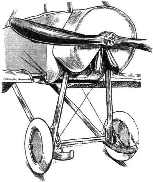
 Winter kordovye velocity model snowmobiles are building in our country, thousands of students avtomodelistov. The interest has Particularly increased in recent Years. It seems that on the ice kartodromo original sports equipment in which it is difficult to know clumsy chetyrehlistnyj snowmobile the recent past.