AIRFRAME F1-A

AIRFRAME F1-AAmong the priority directions of search to achieve the best results in athletes performing in class gliders F1-A, now in a special place is dinamalar — because of its effectiveness and opening new possibilities. And the point here is not only to guarantee additional 10-15 metres in height at the start, immediately after disengagement of a rail. Provide diametrom growth lead to qualitative changes in the tactics of the competition, greatly expanding the possibility of falling in the thermals. Because every additionally recruited a meter of height increases the influence of ascending streams.
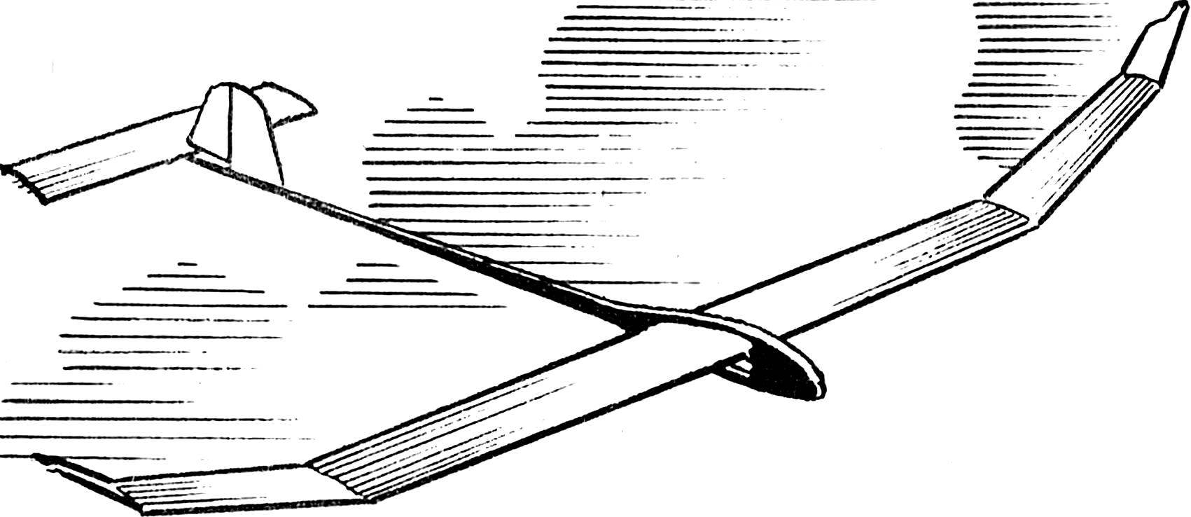
The wing of the model, which brought its creators win at the Championships of the USSR 1989, 1990, success in competitions at the USSR Cup 1990, is a box-like structure. It is made with wide application of composite materials. The caisson of the center section formed of two layers of carbon fabric with a thickness of 0.08 mm with epoxy resin hot curing. The fiber direction of ± 45°. Forming is at a temperature of +180°C, designed for this purpose the electric furnace.
 
Caisson console molded from a single layer of carbon fabric with a thickness of 0.08 mm (fiber direction along the wing) and is reinforced with carbon filaments in the direction of ±45°.
 
The spar is constructed from two carbon-shelves of the same size and the balsa walls with horizontal layers. On the edge of the caisson wall reinforced the balsa with two layers up, with fiber direction 0° and 90°. Section shelves of the spars at the root, at the ends of the center section and the console, respectively, 10,5X0,9 mm, 2,5X0,5 mm and 1X0,5 mm.
 
Of the caisson located inside the balsa leading edge is 2 mm thick balsa noses with a thickness of 1.4 mm.
Fig. 1. General view of the model glider F1-A and the most typical section of the wing, stabilizer (bottom).
 
Fig. 1. General view of the model glider F1-A and the most typical section of the wing, stabilizer (bottom).
 
Ribs made of thick balsa wood with a thickness of 1.4 mm and banded by CFRP with a thickness of 0.2 mm. trailing edge — carbon fiber-thickness 0.8 mm (width in “root” at the ends of the center section and the console, respectively, 3.5 mm, 2.5 mm and 1.5 mm).
 
The wing model is equipped with a removable wingtips R. Whitcomb, reducing the inductive reactance. They are used when flying in subterminal weather. Both halves of the wing are fastened together by one taper pin (steel 65S2VA stamps, heat treatment according to GOST hardness HRC 59) with a length of 160 mm and a diameter of 58 mm (center), 2.5 mm (at the ends). The pin is inserted into the corresponding hole pre-molded in the mold unit of CFRP glued in between the shelves of the spar.
 
Stabilizer models are made of balsa with a density of 0.1 g/cm3. The front edge has a width of 3 mm, rear 8 mm. Shelf rails (section 3X1 mm) made of balsa and reinforced with three layers of carbon fabric with a thickness of 0.08 mm on epoxy resin to the ends of the spars, the number of layers is reduced to one. Between the shelves installed balsa wall thickness of 1 mm. the Ribs and braces have the same thickness. Struts reinforced with carbon fiber. Stabilizer covered with Mylar 6 micron film. The rudder has a symmetric profile. The thickness of the keel at the root 6 mm, end — 3 mm. It is a case design from balsa with a density of 0.1 g/cm3.
 
The fuselage consists of the nose, is made of Stekloplastik 0.7 mm thick, and the tail boom. In front is a compartment for ballast. On the left half of the forward fuselage is a large hatch with a removable cover for free access to all elements of mechanics. In the closed state of the manhole cover prevents accidental disruption of the mechanics from dust and moisture. Inside the compartment is placed tragicomedy timer, the hook for towing and dynamic start, the mechanisms of rebalancing of the wing and “delay”.
Fig. 2. The fuselage with the mechanics.
Fig. 2. The fuselage with the mechanics:
1 — camera ballast, 2 — tubes (D16T), 3 — tragicomedy timer, 4 — Dinamarca, 5 — mechanism “delay”, 6 — mechanism of rebalancing wing, 7 — contour of the hatch, 8 — pin mounting of the wing.
 
Fig. 3. The kinematic scheme of the position of elements of mechanics, and stabilizer.
 
Fig. 4. Removable ending R. Whitcomb.
 
The design of the hook allows to adjust the force of the opening latch, the starting deflection of the rudder, neutral rudder, rudder on tow and in free flight glider. The force of the latch opening is 6 kg.
 
Behind the hook at the bottom of the fuselage contains the mechanism of “delay”. It provides independent adjustment of the deflection angle of the rudder in the first seconds after reset of the Leer and in free flight. The inclusion of this mechanism is a timer.
 
Behind the hook at the top of the fuselage is placed a mechanism of rebalancing the wing. He is driven by a timer and provides the required difference of the angles of the left and right halves of the wing when towing a model on the guard rails and in free flight. The mechanism allows to obtain good handling characteristics of the model with a small aerodynamic twist when towing on the rail, and also allows you to quickly adjust the installation angle of the “internal” wing when towing a model in free flight.
 
Further, at the end of the forward fuselage, placed the camera for ballast.
 
The tail boom is made of two layers of carbon fabric with a thickness of 0.08 mm and three layers of glass, of a thickness of 0.03 mm. the Mass of this part of the structure 13 At the end of the elements of rebalancing the stabilizer with dynamic start. It’s a fungus with the adjusting nut and the hinged bracket with roller.
 
Fig. 5. The tail part of the fuselage.
Fig. 5. The tail part of the fuselage:
1 — pad mount stabilizer, 2 — a fungus with an adjustment nut, 3 — bracket with roller.
 
The mechanics of the model works as follows. When towing on the guard rails of the IPC and the mechanism of “delay” are in the cocked position. While the right “inner” fender has a larger installation angle than the left. Bracket with roller stands vertically and provides a towing position of the stabilizer.
At the start, at the time of reset of the handrail, the hook moves back and turns on the timer. The deflection angle of the hook (and deflection respectively) is determined by the adjusting screw mechanism is “delay”. Model intensive “nose up”. The pitch angle increases to 90°.
 
Using 0.5 s actuates the first timer. The bracket with the roller when it is flipped open. Under the action of elastic thrust, “peredelyvala” rubber stabilizer, the latter is deflected at a greater positive angle. In this model sharply “nose down”.
 
If a strong start this leg of the flight ends when the pitch angle becomes zero with the simultaneous attainment of model balancing speed values. At this point actuates the second timer. Elastic pull (loop) jumps, and the stabilizer is deflected in balancing the position of “planning”, defined the adjusting nut of the fungus. Concurrently triggered “latency”. The rudder and right wing are deflected to the position corresponding to the free flight.
 
After a specified flight time triggers the third timer. Stabilizer together with the fungus rises. The model sits.
 
Implemented in this model a dynamic way to start rebalancing allows you to get a stable start. And increased speed and load on the model require hard wings, reliable mechanics work.
 
E. KOVALEV, master of sports of the USSR, Moscow

Recommend to read

  • TRACTOR AS THE TRACTORTRACTOR AS THE TRACTOR
    F. Slavin from the village Malesina Kurgan region gathered his hands, using the components and mechanisms of various scrapped or abandoned motor equipment.   Engine—DT-25 diesel,...
  • THE TAMING POINTSTHE TAMING POINTS
    A wear glasses only while working or reading. And the rest of the time they are buried, usually in the breast pocket. Just have to bend down like glasses are on the floor. Attach to the...