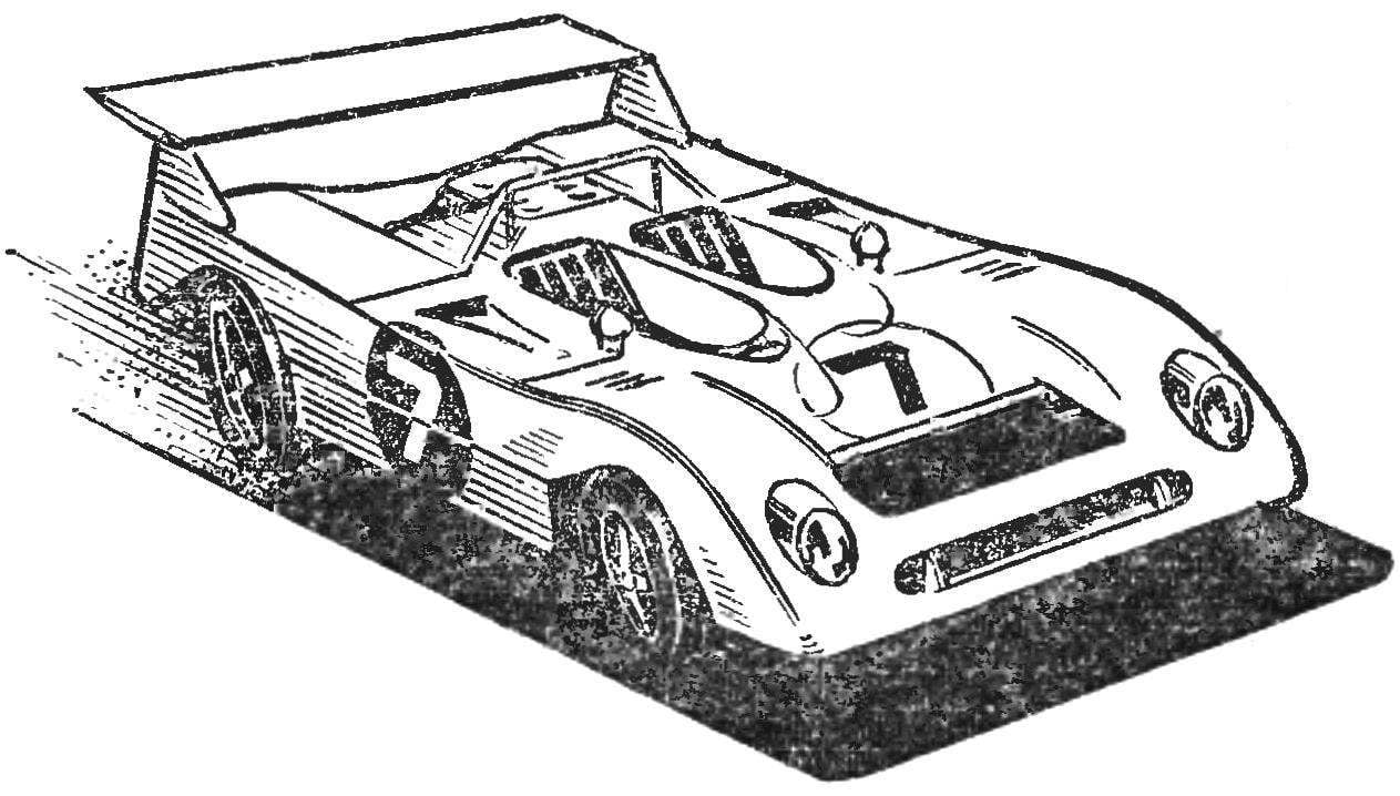
 After publication in the “M-K”, № 1, 1978 of the drawings trace model “Mirage” edition receives a lot of emails from guys who decided to build it. They are interested in some of the “subtleties” of manufacturing technology of the body, its refined forms, ways of fastening of the engine and much more. The editors asked the author of the article “On the track “the Mirage” I. A. Nikolaychuk with the request to share the experience of manufacture and of preparation for the competition.
The body of a car “Mirage M6” is best applied to the wall of thin glass (from a nylon stocking). Cross-section of the body (Fig. 1) will help to make disc. You only need to reduce their sizes according to the estimated thickness of the body. Difficulties can arise when Vileika two closely spaced cockpits and engine cowling: it is practically impossible to ensure their accurate formation, especially the gap between the fairings of the cockpits. It is therefore desirable to manufacture them separately from foam or to squeeze out of thin plexiglass and glue in place. This will greatly facilitate the cutting of the blanks.
The holes for the lights cut out with a jigsaw and finish with a needle file. On the inner side epoxy resin glue foam pieces. They select cavities, which are then glue a Mylar film or other material that simulates light reflecting surface. Of transparent material cut glass headlights, a slightly curve them, pre-heating and glue in the back.
Steaks and a plane wing can be made of a wooden ruler.
The openings of the air intakes cut out after the body putty before painting.
Housing first skraste nitro in white color, seal the plaster circles under the rooms bright and cover with nitroenamel. Without removing the stickers, Polish the surface of the body to Shine. Rooms apply school pen with black oil paint diluted desiccant (nitro dries too quickly, and the numbers will not work neat).
Bench in front of the scene to enhance Shine body useful to wipe lightly soaked in kerosene with a cotton swab and then cover with a thin layer of machine oil.
I want to give some advice to those who have built the model according to the drawings published in “M-K” № 1, tried it and decided to prepare for important competitions. Our experience shows that the most frequent failure in the descent of the model from the route and the drop is otklika controversial plate from the lid of a magnet engine.


Fig. 1. Cross-section of the body of the model “Mirage M6”.

Fig. 2. The mounting of the engine “Norm” on the caliper
Figure 2 shows a variant of the more reliable fastening of the engine of the “Norm” to the bracket, recommended for more experienced modelers. First of all slizovskiy, somewhat away from the edge of the cover of the magnet, above and below— is strictly parallel to the axis of the engine in a plastic shell, saw through the grooves to the surface of the magnet. It is important that the sides of the groove were not “spaleny”.
The bracket lignite thus to sleep in the slots with some interference. The gasket provides a preload in the axial direction.
I want to say a few words about the tire model. From the theory of the vehicle is known (and what is the trace model is not a small car!) the value of resistance:
Pf=Gf,
where G is the weight of the model, and f the coefficient of rolling resistance. The harder the tire, the lower this ratio (f = 0,08—0,1 for solid tires and 0.11 and 0.12 for soft), the faster the model moves at the same power of engine.
On the other hand, the competition on the track is crucial to the ability of the model to overcome many turns without significantly reducing speed. Estimated calculations show that the real danger is for the model only skid the rear wheel, as the rollover, even without taking into account the effect of the leash can happen at a speed far exceeding that which normally moves the model.
The rate at which skidding does not occur, is determined by the formula:

where Rпов. — turning radius,
g — acceleration of gravity, μ is the coefficient of lateral adhesion, or coefficient of resistance to movement of the model in the radial direction.
To increase the coefficient μ, the tires on real cars made CoE special protector, often very complex shapes. However, for tyres EN-route models to fulfill the protector extremely difficult. The easiest way to increase the lateral grip is to use soft tyres from microporous rubber. But such buses inherent another drawback is the high coefficient of resistance to rolling associated with the fact that the radial rigidity of the tire is insufficient.

Fig. 3. Bus “sandwich”:
1 — axis (needle Ø 2 mm), 2 — inner cheek (button), 3 — layer microporous rubber, 4 — strip (Whatman), 5 — outer cheek (button).
We offer the design of the tyres free from the above drawbacks, which the boys called “sandwich”. The tire (Fig. 3) make three circles microporous rubber with two strips of heavy paper (Whatman). All the details of bond rubber adhesive. When assembling the model, squeeze the tire with the cheeks, resulting in a microporous LUT slightly and the wheel diameter will increase. “Extruded” beyond the paper strips mass of the rubber works as a soft protector, and the whole bus design with low weight retains sufficient rigidity.
When testing the model with these tires on the track with the “sand” coating the turns with a radius of 30-40 cm were overcome without speed reduction.
I. NIKOLAICHUK


