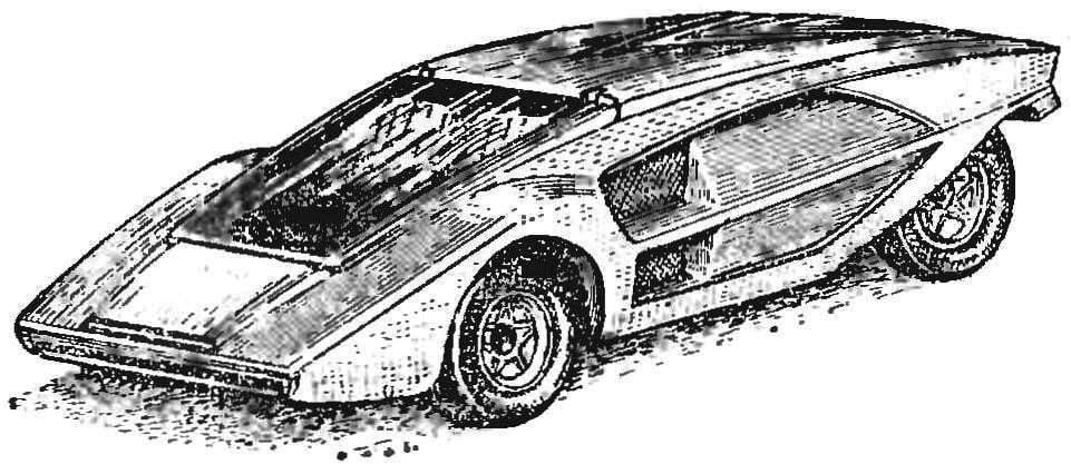
 Have trace modeling particularly attractive trait: despite the relative simplicity of the models, they give space for the creative work of the children’s thoughts, development of design imagination. An illustration of this situation can serve as our mug on the car model “Stratos” (Fig. 1). Recently Moscow plant “Young technician” started to produce the engine of DP-15. He has two obvious advantages: its capacity is sufficient to move the model, and it is quite affordable. Another plus: when calculating gear, you can focus on the spur gear for electric shavers that are sold as a spare . parts. Cons — size and weight — when novice modelers can not be ignored.
The engine and gearbox at once determine the choice of prototype to copy: a car with closed wheels (p — tracking).
Figures 2 and 3 presents a drawing of a model developed in our group, based on the above assumptions.
At first glance, the model seems complicated, and the number of parts is too large. The task could be solved much easier by applying a panel frame made of sheet duralumin, flare, into the holes of which are inserted the axis of the wheels and idler gear. Indeed, one such frame can replace from about 10 parts, but its layout and production of long children is not easy.
In our opinion, the proposed design is suitable because of the simplicity of each individual part. Size, requiring in the manufacture of unconditional accuracy, a little, they are adjusted in place. If failed item, it is not a pity to throw it away and in 3 minutes make a new one.
You should start with the sub-frame. The arch drawing parts 33 and 39 and connects them together, as shown in the drawing. Cut sheet from the support pad 26 and 29 with allowance for the bend, gently bend at right angle side and a small amount of tin to grab a frame only the side spokes lying closer to the center of the model. With scissors cut off the excess seam allowance, compress the flanging pliers and probailout completely. Then grab the solder of the spacers 51. Cut curve on the motor and solder the walkera 38. Punch in the sites of the holes for the clips. Soft arch clip fasteners 18 in the form of the letter P, is inserted from below into holes made at the ends of the hooks, then cut off any excess wire.
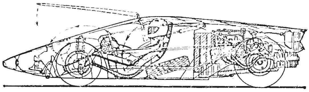
Fig. 1. The layout of the main units and the location of the driver in the car “Stratos”.
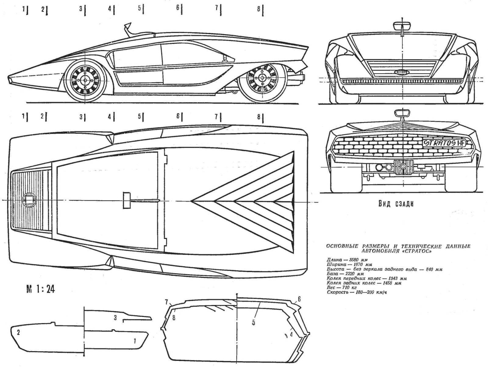
Fig. 2. The appearance and cross section of the body of the model car “Stratos” (1:24 scale).
Inserting the gear 48 of the bushing 19 securely soldered it to the motor shaft, trying to fill the teeth solder. The engine is mounted on the sub frame and rack clamps tightening a thin, flexible wire. Under the rack you can put pieces of thin rubber.
Gear 43, which plays the role of parasitic, it requires some finishing touches. Drill Ø 6 mm, clamped in a vise jewelry, rassverlivajut (diameter drills can be increased gradually) axial hole. In the recess insert ball bearing with outer Ø 8 mm and the thrust sleeve 47. As the axis it is better to use the suitable screw with a locking nut. Contra the bearing pin 14 and a spring ring 13 (the latter is a set of gears).
Rack idler gear 21 is cut from sheet metal, and bent for rigidity hocus the contour of the wire. After this is inserted into the hole axis of the gear and tighten the nut. Assembly put on the frame, providing the necessary clearance in the engagement, after which the rack is brazed.
In another embodiment, the pinion without the alterations put on a smooth axle, which is soldered or between the two cheeks of the rack, or console soldered to one cheek.
Manufacturer of rear axle does this.
Contact the smart host is the most critical part of the model. Its mission is to provide the maximum reliability of current collection. Sawed plexiglass leash 10 has three holes Ø 1 mm for planting with tightness of beams _ of the lever 15, 23 and 50. One of the holes drilled “into the body” to the longitudinal axis to a depth of 2-4 mm, as shown on the dash. Protruding from the holes ends should be grinded needle files. The rear ends of the beams are soldered to the sleeve 27 and in the middle of the beam to reinforce the screed 22.
Leverage the current collectors 12 a jigsaw cut out of Plexiglas or Micarta and drill or puncture holes. The current collectors 11 with soldered wires securely bolted to the levers of thin copper wire (ends of the wires after the twist to bite). The levers and the adjusting sleeve 7 are sequentially placed on the axis passing through the leash, and fasten the nut. Bushings 7, you can adjust the position of the current collector width of the current-carrying bus. The levers should be rotated on the axis freely.
Cut tin earrings 16 is collected at an axis 49 with contact-the guide node, tightening the nut and solder to the underframe. Then loosen the nut slightly so that the lever freely rotates on the axis.
Front axle 2 wear of the axial sleeve 3, the restrictive washer 4 and the tube 6. The latter should have a relaxed fit and rotate easily. Restrictive washers soldered.
Aeromodelling round the butcher 9 threaded in the eyelets of the levers of the current collectors, is passed under the tube, is slid under the plate around the sleeve and fixed to the engine. Gum performs, as can be seen from figure 2, three functions: creates a small torque on the lever of the collector that bridges the gap between the current collector and the current-carrying bus, pogressive from below the front axle and, finally, loads the moment the leash, which thus remains in the guide groove when you bounce the front of the model.
It remains to make a support 36 and solder it in place.
The choice of the prototype for the copy of the body, perhaps the most pleasant operation in the construction. As we have already mentioned, it is the desire to reproduce the forms of the beloved vehicle is often the cause of passions trace modeling. That’s why it is better to simplify the geometry of a model while copying than it does to reject it due to the fact that you have little faith in the ability of 13-year-old Modeler with sufficient accuracy to reproduce some bending of the housing.
In this respect, especially the “unlucky” models of class C (closed wheel body is of the usual type), copy these models difficult, and very popular, they do not use, because their design lacks the details that adorn the appearance of a small car.
When the question arose about what to choose as a prototype to copy the shell model with covered wheels, all our guys unanimously named experimental vehicle italiskai company “Lancia” “Stratos” (Fig. 1 and 2).
Wedge-shaped body of the machine is striking in the strict logic of the lines. “Stratos” immediately attracts attention as the uniqueness and elegance of appearance: think of the shape of its stingy, but they have maximum expressiveness. Even in the drawing, housing all projections of the full dynamics, but the rear view gives the impression that the car is rapidly moving away from you.
Aerodynamic contours “Stratos” is so perfect, efficient airflow the engine is carried out using the conventional blinds, as the air flow approaches nezamechennym. This machine has its own peculiarity — it’s the lowest in the world, its height is 84 cm (about the height of the gas stove).
It is hard to imagine a better prototype for the trace model — broad gauge acceptable base, wide rear wheels, enough space inside even for a motor-mastodon as DP-15. Small side Windows at the “Stratos” flat and the front is only slightly curved. This immediately removes the necessity to manufacture complex stamping blanks length of the glazing.
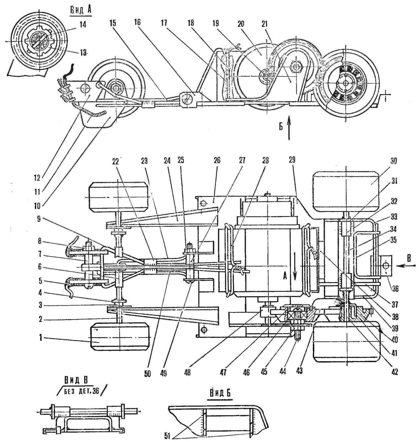
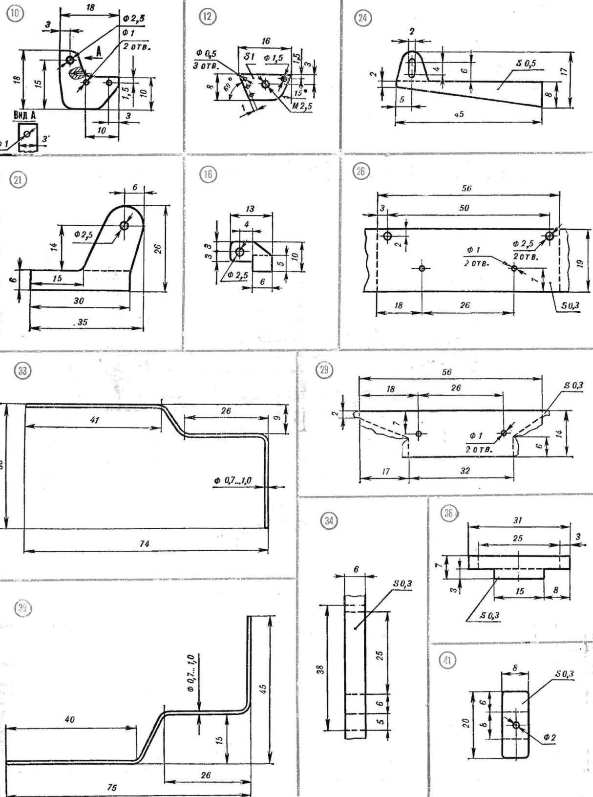
Fig. 3. Chassis model (body shot):
1 — front wheel Assembly 2 — front axle (a knitting needle Ø 2 mm), 3 — axis bushing (polyethylene tube by the rod of a ballpoint pen), 4 — thrust washer, 5 screw M2,5 l = 15 mm, 6 — tube (a plastic tube), 7 — the adjusting bushing (polyethylene tube) 8 — nut M2,5, 9 — band, 10 — lead (plexiglass thickness 3 mm), 11 — collector (wire braid), 12 — arm current collector (Plexiglas or Micarta thickness of 1.5 mm), 13 — snap ring 14 — pin (white sheet or flattened wire), 15 — upper beam (needle Ø 1 mm), 16 — earring (white tin), 17 — a lining (sponge rubber), 18 — clip (paper clip), 19 — Bush transition (copper, brass), 20 — motor DP-15, 21 — front idler gear (tinplate), 22 — screed (tinplate), 23 — right beam (needle Ø 1 mm), 24 — bearing, front (tinplate, with amplifiers from the spokes), 25 — nut M2,5, 26 front, base area (tinplate), 27 — Bush bearing (tube with internal Ø 2.5 mm), 28 — coupling retainers (wire), 29 — rear support pad (white tin), 30 — rear wheel Assembly, 31 — washer resistant, 32 — rear bearing (copper and brass tube) 33 — right polurama (needle Ø 1 mm), 34 — bracket (white tin), 35 — stiffener (clip), 36 — rear bearing housing (white tin), 37 — support bracket (needle Ø 1,5—2 mm), 38 — emphasis engine (tinplate), a 39 — polurama left (needle Ø 1 mm), a 40 — driven gear Z = 43, 41 — led (white tin), 42 — axis (needle Ø 2 mm), 43 — idler gear Z=43, 44 — screw M2,5 l=12, 45 — nut M2,5 (2), 46 — ball bearing Ø 8X2,5 mm, 47 — resistant sleeve (can be made by cutting off the end cap from a ballpoint pen), 48 the leading gear Z = 11, 49 — screw M2,5 1 = 15 mm, 50 beam left (needle Ø 1 mm), 51 — spacer lower (needle Ø 1 mm).
The casing can be run entirely from foam. From below, you should select the cavity is sufficient to install the chassis. Through holes are cut under the windshield and under the side of the recess. Inclined planes in the last simulated inserts of cardboard. The housing is coated with epoxy, putty and paint vivid nitroenamels.
Note, however, that with this method of making housing difficult to achieve that it was inherent in the prototype greenest, in which the cross section of the housing is not formed curves drawing curves and straight line segments, connected by relatively small radii. It is difficult to accurately perform a complex swage line on the roof of the car to the frame of the windshield. Therefore it is better to make the body by the reverse veclachi of epoxy resin and fiberglass. To do this, first right on drawing, make a wooden disc (naturally, without side grooves), the plane of the connector provide on the main diagonal of a side.
On each half after coating the surface of the wax-mastic is made from steklobloki and its tough resin matrix. The inner surface of the matrix is finished, smeared with mastic, and it has finally vyklevyvajut ladles of the corps. Then cut out the necessary holes, ladles glue, mimic grooves, louvers, etc. After painting and polishing the hull glued lugs with threaded holes. Into these holes screw bolts, tractor body to the underframe. The third back support screw screwed into the part, simulating a box of speeds.
We have not said anything yet about the wheels. Experienced modelers can produce their discs on a lathe and polished. You only need to provide a reliable torque transmission from the axle to the wheel. An easier way is to use circles, sponge rubber, compressed cheeks, buttons for clothing (see “M-K” № 1, 1978). A small button plays the Central part of the wheel however, it is desirable to provide the remaining elements of the cap. Best method: machined to size and polished the neck of the tube of toothpaste paint to complete the required blackening, turn it to the rubber button, and a button soldered to the axle.
When supriyaji and chassis critical is section 8. Since the thickness of the shell model regarding much more than a real car, with accurate scale rear wheels will be sure to cling to. Therefore, it is advisable to slightly reduce the width of the rear wheels, or slightly to narrow their rut.
The model is particularly “works” on the tracks with a small number of high-speed sections and with a large number of turns, since the center of gravity made a number of forward vs normal, which reduces the likelihood of a strong drift.
We hope that our “Stratos” will not fail you at the competition!
THE PAINT SCHEME OF THE MODEL
Building — brick-orange, Venetian blinds — black, rear grill, black, glass tinted in blue, the plane in front of the windscreen is white with thin and frequent black stripes. Heraldry on the prototype is missing. In front there is only brand of the company “Lancia” blue, the tires are a common brand of the company.
The hubcaps are chrome-plated only radial spokes. Exhaust tips are chromed. The tread pattern is close to the wafer.
I. NIKOLAICHUK
Recommend to read
 CALL THE NIGHTINGALE
Probably you happen to see this picture: all the appliances in the apartment turned off, and the meter disk rotates slowly. It turns out that the culprit door electric bell: its primary...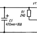 ATLANTA ELECTRICAL CIRCUITS
Who used a portable transistor radio, know how, over time, decrease the sensitivity and loudness of the radio, begins to "float" the rate of advance of the tape in the music player... ...
