
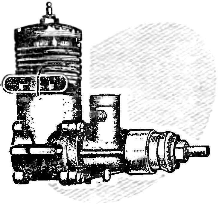
 Engine MD-5 Kometa is produced in large series for many years and is established on the models of different types. To simplify manufacturing and reduce the cost of manufacturing allows derogation from increased individual adjustment of the prototype. This leads to the fact that the production engines develop power below possibilities inherent in their design. Only individual samples with the perfect mix of details showing good results.
Most often the modeller is interested in how to increase engine power. Here are some proven tips.
Conducting preparatory and staging of work (see “M-K” No. 4, 1976), start refining the details.
Carter — the most important of them. Some of the engines of the first releases of the width of the passageway was insufficient, and part of the bypass of the Windows in the sleeve overlaps the wall of the housing. This greatly reduced the engine power. If you were a Carter, you need to widen the canal at the height of the overflow window casings. Work is performed using a large cylindrical dental burs (cutters), clamped in the Chuck (mandrel or collet) table lathe. A flexible hose from the drill better not to use the cutter loses its stability, “runs”, and the surface is “crushed”. The upper part of the channel process via the exhaust pipe, holding sump for rotating the cutter and moving it. It should be noted that the cutter tends to move Carter in a direction opposite to the cutting direction, and therefore it must be kept tight (steadily), only slightly pushing on the cutter.
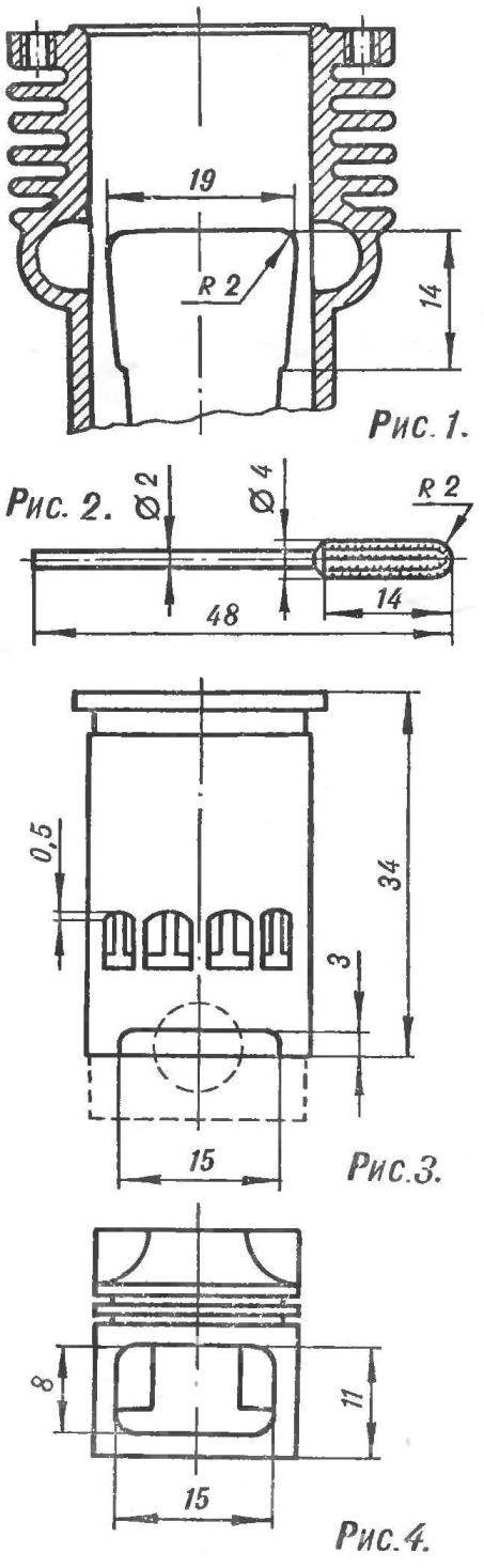
In the processing of the passageway ensure that the cutter did not increase the height of the upper edges, and the edges had not been overwhelmed, because this can adversely affect engine operation. Metal can only be removed from the side walls. The final shape and dimensions of the upper part of the overflow channel is shown in figure 1. Figure 2 shows the cutter with which the work is carried out not the crankcase and piston.
Insufficient cleanliness of processing of the overflow channels, sharp edges, looking inside the crankcase, a sharp transition lines — all this increases hydraulic resistance, and therefore reduces the rate of passage of the mixture during the operating cycle. Therefore, all transitions there should be smooth. After pre-processing the cutting tool surface cleaned with sandpaper and polishing paste GOI.
Sleeve engines of the first issue had an increased length, making it difficult for the passage of the combustible mixture during bypass. To avoid this, the lower part is recommended to be modified as shown in figure 3. (Sleeve engines of the latest release in this incitement is not needed.)
To facilitate the working conditions of piston rings the upper edges of the exhaust and the inlet ports give the “arched” shape. Regata window should not increase by more than 0.5 mm. Jumpers purge Windows from the outside make oval. Jumper exhaust Windows process is not necessary. The lower part of the liner under the vent Windows take the edge off, and then cleaned with sandpaper and polished.
The inner surface of the sleeve to reduce mechanical friction losses and increased engine recommended chromium coating.
Coating thickness — 0,01 — 0,015 mm.
After installing the sleeve into the crankcase upper edge of the inlet ports must match exactly with the edges of the channel. When they mismatch you will have to trim the mounting plane to the crankcase of the engine or put the gasket under the flange of the sleeve.
Insufficient fit of the sleeve into the crankcase to prevent losing gas in the exhaust pipe before final installation, coat the outside with glue BF-2.
The piston engine is made of aluminum alloy AL-4 and has two compression rings from high-alloyed CR-Ni cast iron CNV. The weight of the standard piston (without the rings) is 5.5 g. This is a very good weight figure for the engine of this displacement, and therefore the detail to facilitate is not needed. Refinement is the polishing head and increasing the openings from the side passageway to the dimensions specified in figure 4. During the polishing, the heads need to be careful to avoid “blockage” of the top edge, it will worsen the working conditions of the top piston ring and could lead to its “occurrence” in the groove. It is not recommended to remove metal from the lugs and to reduce the length of the guide holes of the finger. Failure to comply with these conditions will inevitably lead to overheating and jamming of the piston at high rpm.
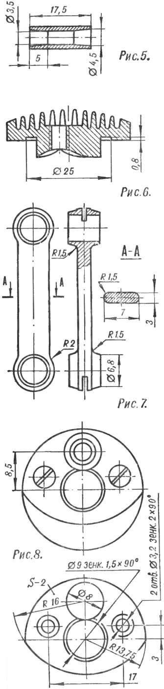
The piston pin should not be shortened and equipped with plugs, as sometimes recommended. This will contribute to rapid and uneven wear of the fitting holes of the finger in the piston. If desired, it can be easier (weight standard 1.8 g), increasing the diameter of the inside hole to 3.8— 3.9 mm, or treating a conical scan (or needle files], as shown in figure 5.
The cylinder head face piercing holes (see Fig. 6), and the surface of the combustion chamber sanded with fine sandpaper and polishing paste GOI. When finishing work must be taken as the standard strip thickness of 0.2 mm changes the compression ratio by 0.8 units. When compression ratio 10-11 selected parts of the head require further refinement.
The connecting rod has a large margin of safety and considerable weight (3.7 g). It is brought on the mandrel on a lathe (manually or needle files) until the bar size 3X7 mm. Then dull the sharp edges, sanded with sandpaper and polished. Final dimensions of the rod — figure 7. A rod with specified size never stopped even at high speed.
The crankshaft is polished inside and sharpen the edge of the intake window in the same way, as did the engine “meteor” (see “M-K” No. 4, 1976). Day reduce the volume of the crankcase and reduce hydraulic losses on the cheek provorachivayut shaft with two screws M3 plate (Fig. 8) made of aluminum, which height becomes a “flush” with the protrusion of the counterweight.
The toe of the crankshaft. Inlet make a rectangular shape with a size of 8,5X11 mm with a radius at the corners of 1 mm.
The diameter of the diffuser of the carburetor is increased to 7.5 mm. cross-Section of the hole from the narrowest part to the intake box by doing the expanding, rectangular in shape. To relieve the maximum power of the diameter of the diffuser should be at least 9-9,5 mm.
The nozzle is polished on the outside and next to the standard hole Ø1 mm drill two (left and right) of the same diameter. The needle is a little focus and Polish.
When operating the engine on fuel with no additives (methyl alcohol 80%, castor oil 20%) the compression ratio of 9-10. As shown, for best results, each motor requires individual selection of compression ratios, depending on the composition (recipe) of fuel applied to the candle type, diameter, atmospheric pressure, etc.
Prepared according to the above method engine standard fuel capacity 0,75—0,80 HP at 18000 — 19 000 rpm.
Recommend to read
 THE ARRANGEMENT OF THE GARAGE
Garage for car enthusiast is not only a roof for cars, but also a place where we have to spend a lot of time: it is necessary to embellish the body, oil change, and even to engage in... COMFORT BEGINS WITH A HANGER
You enter into your apartment, whether to visit, the first thing that greets you when you walk through the door, the hallway or the front, as it is called. In modern homes it is usually...
