CONTRARY TO TRADITION

CONTRARY TO TRADITION“Made without balsa? Then bad!” — is unexceptional opinion about aerobatic traditionally there is a perception among most athletes. Especially categorical estimate the model from the point of view of its material beginners — experienced only pilots first, to clarify, do not use fiberglass.Maybe you shouldn’t be so categorical in his judgments
only “dress for success”? Ultimately, all flight properties of the model do not depend on the used materials, the main thing — successful, from a design point of view, a well-designed power and aerodynamic configuration.
An example of this is the proposed flight, which can be collected even on the kitchen table from readily available materials.
To reduce the forces that prevent the rapid reversal in the “corners” of the square shapes of the complex, is the task we tried to solve when designing this model. Here’s how we reasoned. If aerodynamic effects have a double impact on the accuracy of sharp reversal, then a significant separation of the masses only harmful. Aerodynamic damping makes it difficult to rotate the model, but it also helps dramatically to stop the rapid rotation after the transfer of the rudders in neutral. Imagine the impact of the spacing of the masses can, trying to spin and quickly stop the long rail. While she hung, will make it easy. But as soon as the ends appear a small additional loads (even much lighter than the weight of the rack), the hand will immediately feel the difference. The same happens on the model. Adjusting the elongation of the fore part, carrier motor, or a dozen extra grams on the tail completely changing the nature of governance. Pilotage not only be “sluggish” with a sharp cottage rudders — it is much more difficult to stop the rotation started, she did not immediately go into a straight flight after the rudder is in the neutral position. To what extent can seemingly save the day, shifting the CG back, that is, decreasing the stability margin at the angle of attack. But look where it leads: an additional download of a tail part will exacerbate the effect of the spacing of the masses, and a heavy engine will be at a greater distance from the center of gravity of the model. As a result, the controllability is not improved, and the stability of the apparatus during slow withdrawal from the figures in the direct flight will decrease, management will become more difficult.
 
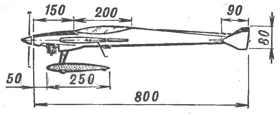
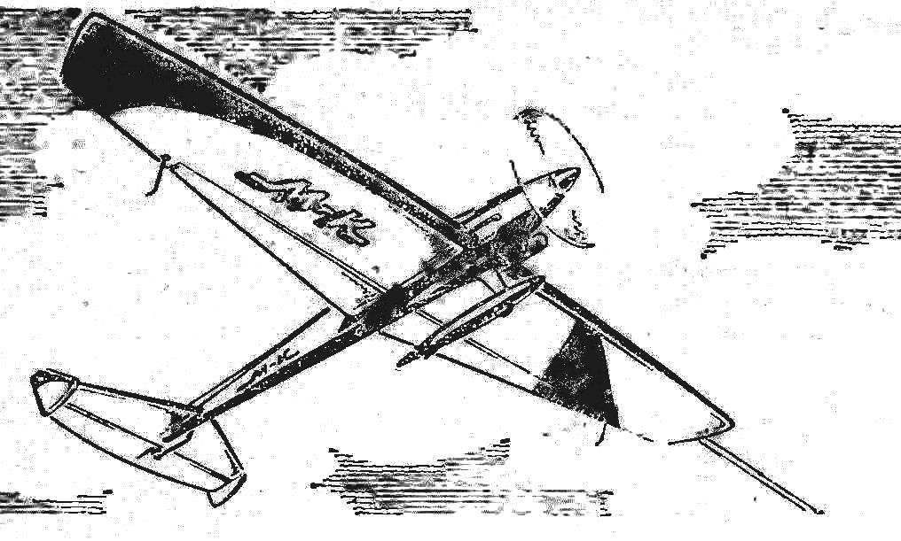
Fig. 1. An aerobatic control line model airplane.
 
We came to the conclusion that it is necessary to significantly shorten the nose of the fuselage and simultaneously reduce to the limit the weight of the tail. We also considered that the impact of the spacing of the masses is primarily determined by the distance between the centre of gravity within the formula of moment of inertia in the second degree.
 
Fig. 2. The load bearing plane
Fig. 2. The bearing of the plane:
1 — Klondike solitaire (1 mm plywood), 2 — wakantanka pine (9X9 mm), 3 — guide for the control wires (spring wire OVS d 0.2 mm). 4 — the front edge pine (18X25 mm), 5 — control cable d 0.5 mm, 6 — rib (lip thickness: 2 mm). 7 — hole for rack mounting the chassis in a two-column version, 8 rocking control (D16T with a thickness of 2 mm in all holes, a steel tubular rivets), 9 — Central rib (lip thickness 6 mm). 10 — fuel tank 11 — rocking bracket (U-shaped wire OVS d 2.5 mm, soldering from the inside to the tank wall). 12 — Powerware (lip thickness of 5 mm), 13 — strengthening stenn back .Romka (Linden), 14 — bracket, flap control (wire OVS d 2.5 mm), 15 — boss mounting bracket (Linden), 16 — flap (foam PVC 2 mm thick), 17 — rear flange (pine 2″5X12 mm). 18 — a wall edge (pine 1X12 mm), 19 — sewing the Central part of the stabilizer (lnpa thickness of 0.5 mm) 20 — stabilizer Assembly 21, the Elevator Assembly 22 and the boss mounting the horn, 23 — trim center – (Linden thickness 1.5 cc, a layer of wood parallel to the span, in Anda on top of the upper cladding not shown).

 
It turns out, for example, that the engine weight of 200 g, located 100 mm from the center of gravity and balanced load of 20 g on the shoulder, 1000 mm, has ten times less influence in the handling than the weight-balancer!
 
Calculations show that for pilotage the distribution of mass along the length of the fuselage — the main factor of controllability and flight properties. Recall the experiment with the rake. And try to repeat it for the time required for microgravity for the passage of the “corner” of a square or triangular shape, that is, for a tenth of a second!
 
Fig. 3. The principal dimensions of the model
Fig. 3. The principal dimensions of the model.
 
The design of the new model began with the selection of the main parameters of aerodynamic configuration. We took polulineinogo type with a wing of large aspect ratio with a strong shoulder stabilizer. Such a design provides good handling with high stability of the model, the long wing reduces the loss of speed in some parts of the figures.
 
The fuselage turned out unusual for modern “protectrate” design — with an extremely short nose. Its basis are two flat lime side, docking in the Assembly to mounted on the wing bars motor. The nose of the fuselage deformeaza the top and bottom half of the “bonnet” carved from basswood and glued to Motorama, side walls and the frames. Then installed the tail boom rails, bar mounts, chassis, tail rack ribs and the lining under the stabilizer. Paste “polik” cabin after the debugging of the control system, installation of the bottom skin of the fuselage is not affected ka the sequence of operations.
 
Fig. 4. The fuselage
Fig. 4. Fuselage:
1 — spinner, 2 — bearing cradle engine mounts (birch 7×13 mm), 3 “cowl> (Linden), 4 — the front frame (plywood 2.5 mm), 5, 7 — frame (plywood 1.5 mm). 6 — light (Plexiglas of thickness 0.5 mm). 8 —hole cover in the “police”. 9 — top stringer (pine 4…8 mm). 10 — keel, 11 — solitaire mounting stabilizer.12 — tail boss (Linden).13 — the lower trim of the tail boom (LNA 0.8 mm thick layers across the fuselage) and 14 bottom stringer (sosia 4X4 mm). 15 — the rear triangular frame (slats 2X4 mm, casing is not touched), 16 — side panel (lime 2 mm thick). 17 — boss of the rack Mount chassis (lime). 18 — cone, 19 — landing gear Assembly 20 to the wheel 21 — a nut of fastening of racks of the chassis (glued to the boss), 22 — the loop holes in the “police” under the bracket of the drive flap.On the top view details POS. 3 6 conventionally not shown.

 
Wing with a design scheme reminiscent of a plane rumble. The leading edge-spar pine, in the root section of the billet 18 x 25 mm, by the end of the console, it decreases according to the chord twice. The weight of such edges after refinement of the profile is significant — about 150 g. However, if we consider that the fuselage is very light, and the tail is literally “down”, why not invest the excess mass in advanced, durable, located near the center of gravity of the edge-spar! This item is even useful — it increases the moment of inertia of the roll. The unusual profile! Too thin! As shown by the first tests, we can safely reject these doubts! A simplified profiling has not given any significant deterioration of the flight properties of a thin profile has provided the ability to create flexible (only up and down, twist the console was surprisingly hard) wing, further improving the characteristics of the model at sharp evolutions.
 
Fig. 4. The partitioning ribs and edging-spar
Fig. 5. The partitioning ribs and edging-spar
 
Trailing edge… Like when rendering all other elements, especially taken into account the distance from the center of gravity. Therefore, the edge is made of lightweight, in the form of the letter T. It allows deflections to withstand the tension of the skin are rarely delivered between the ribs. The frame of the wing is closed solid pine endings associated with the front edge of the plywood flush with the rails, with the rear flange supported by a light scarf.
 
Fig. 5. A control scheme model
Fig. 6. The circuit control model:
1 — rope control 2 — rocking chair 3 — pull the drive flap. 4 — hog, sacralgia, 5 — drive bracket flaps. 6 — rack-traction. 7 — pylon rudder.

 
A slight bend of the edge of the spar formed with the Assembly — by tightening the shanks of the tip trailing edge. This technique compensates for minor inaccuracies of installation parts according to the angle of attack. Rib cut with minimal allowances, shall be pasted in the assembled power circuit after curing the adhesive connecting it, the joints of parts are reinforced with triangular strips.
 
R and p. 6. Fuel tank
R and S. 7. Fuel tank (tinplate tin thickness 0.2 mm).

 
The order of Assembly of wing center section: strengthening of the rear edge of the fuel tank with the host rocking the control rod the flaps, the Central rib from the two halves (upper and lower) and polonaruwa, covering the center section. After assembling the frame, pasted the output nodes of the control wires in the right hand console incorporates a weight of 15 g, and then carefully set the bars motor and they are stuck with the M3 screws for mounting the engine.
 
Flaps extremely lightweight construction. Due to the significant contraction and, accordingly, a large width and thickness at the root they are rigid enough in torsion. The best material for the edging of the flap is necessary to recognize the balsa, although satisfactory results can be obtained with thin lime strips. The task of edging to protect the foam from exposure to temperature when tight Mylar film and how to “push” the leading edge of the flap lining. From the last dam on the side of protecting the lightest polonaruwa not related to the skin.
 
Horizontal tail design repeats sacriliege goals. Note that their main function is not to improve the appearance of flight, improving the efficiency of plumage: removed limit of flow at significant angles of deflection.
 
Chassis Cycling scheme. Stand design is clear from the figure, the pen plug carries a small wheel like the “racing”. The tail part fairing with the “heel” firmly holds the tail of the model from falling on the takeoff and landing, and roll to prevent lightweight crutches lumps on the consoles. We have abandoned the conventional two-gear, as it provides an increased resistance and reduces the symmetry control on direct and inverse figures. At the same time managed to do without long and relatively heavy tail of the crutch with the attachment point on the fuselage.
 
Fig. 7. Stoick chassis
Fig. 8. Stoick chassis:
1 — bracket (D16T, “channel” modified), 2 — cheek (D16T 1.2 mm thick), 3 — spacer (3 mm plywood).
After assembling the stand, on epoxy glue on the blind rivets to the vertical part of the handle until the elliptical cross-section and winding nylon thread with epoxy turn to turn. Console “whiskers” to wrap the yarn, gluing to the inside walls of the fairing.

 
The control system of conventional type, it is necessary to mention a different length leashes in a neutral position. This difference is equal to 103 mm and serves to protect the carbines from the cord grip.
 
Covering all models from metalized Mylar film on the glue BF-2. The only exception is the fuselage. To increase the torsional stiffness he sheathed cable with paper of medium thickness. The keel is mounted after trial runs and serves as a load that allows precise adjustment of the position of the center of gravity.
 
The alignment indicated in the drawing. You may need to change its position to achieve
maximum stability and handling. However, it should be noted that the value provides an excellent combination of these characteristics at the quite front the value of about 24% SAH {critical alignment polyplanar such schema corresponds to approximately 35 %!).
 
The engine serial Microdrive KMD-2,5 and wooden propeller 230 X 130 mm and a tank volume of about 80-100 cm3 pressure. We believe this power system the most reliable, especially as to get from “diesel” at least a little bit satisfactory double-declutching on figures is impossible. But mode on all figures, Podaca fuel from the tank under pressure reliable, it does not change as production of fuel, and ka clear “corners” reduction in speed is not so noticeable.
 
V. KIBETS

Recommend to read

  • SHOE COMBINESHOE COMBINE
    Four boards and four brushes is all that is required in order to in the hall of the rural house or cottage has a very convenient fixture for shoes. Thanks to him, easy to remove even...
  • CUT “HEAVYWEIGHTS”CUT “HEAVYWEIGHTS”
    The eternal conflict of needs and means of their realization was particularly glaring after the start of construction of the "Washington" cruisers. Desyatitysyachnye high-speed ships are...