
 New technology for the manufacture of model airplanes, primenyal the modelers of the GDR from the city of Erfurt, the magazine introduces readers to No. 6 in 1977. Today we tell about the well-proven original management system stabilizers models of gliders. I hope that the Soviet model airplanes with interest acquainted with the design of the control mechanism and get it on “weapons” in their practice.
In recent years, RC models of gliders is more common T-shaped and V-shaped (Fig. 1) plumage. This scheme has certain advantages over the traditional classic is important, in particular, that high mounted stabilizer less susceptible to damage when landing. Our modelers believe this scheme is the most successful.
We offer two versions of the actuator for rudder V-obrazova stabilizer: lever (Fig. 2) and the slide (Fig. 3).
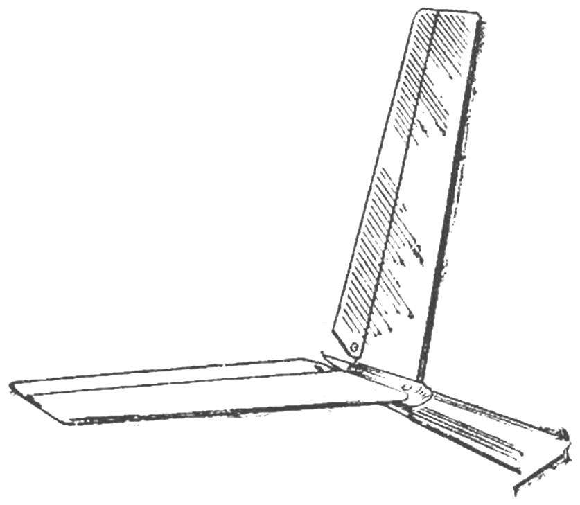
Fig. 1. V-tail model glider.
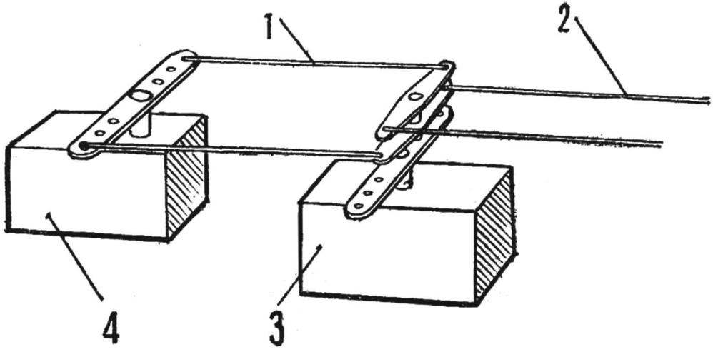
Fig. 2. Scheme lever drive:
1 — pull, 2 — traction control system 3 — servo side of the rudder, a 4 — servo motor of the Elevator.
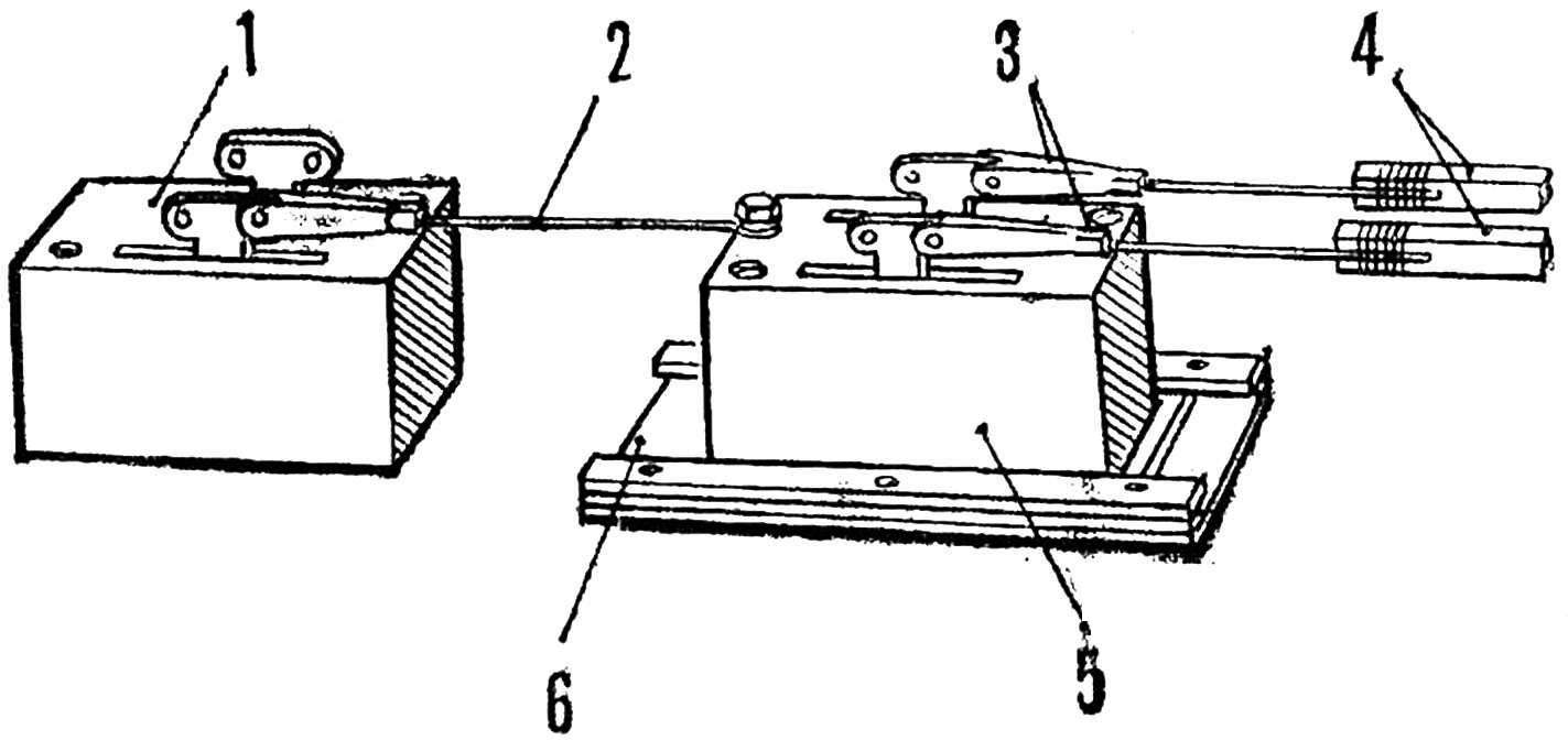
Fig. 3. Drive by guides:
1 — servo elevators, 2 — rod, 3 — forks, 4 — rod drive to the control system, 5 — servo side of the rudder, 6 — the guide servo.
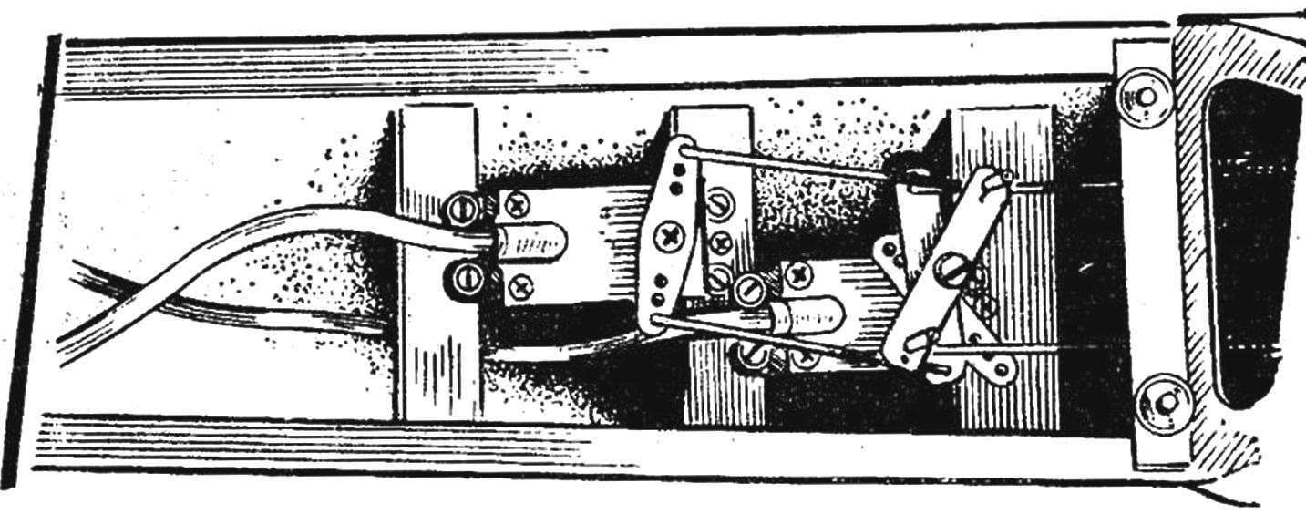
Fig. 4. The layout of the lever drive
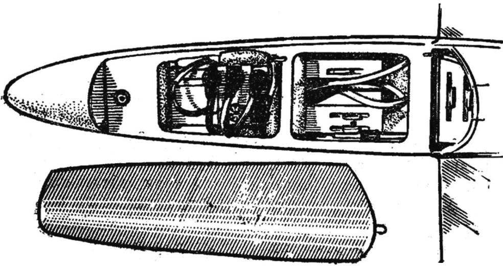
Fig. 5. The placement of the equipment slide type on the model.
First it is more convenient to use for servos with vertical shafts terminating in duplicity levers or round sleeves with hole, mi. The differential drive mechanism consists of two located one above the other levers movably ukreplennyj on the axis installed in the eccentric sleeve (lever), right hand steering cars (see Fig. 2). The amount of offset of the axis depends on the required displacement of the steering rod. To the free ends of plastic or metal levers attached to the rod. This option has the advantage that the servos can be firmly and securely fixed in the fuselage of the model in case of failure (abrupt) landing.
The second option is suitable for cars with a steering lever mounted PA a horizontal shaft (see Fig. 3) and having a longitudinal movement. Servo is installed in the guides and can move in either direction through the rod. Pay particular attention to the movement occurs easily and without backlash.
Both options control the V-neck stabilizer have proven themselves in practice.
Placement and layout of the radio equipment shown in figures 4 and 5.
G. MILES, A. SCAR, GDR
Recommend to read
 CRUISER UNDER THE “TRIDENT MISSILE”
Unlike Britain, the United States emerged from the Second world war, not only without any significant losses in the cruising part, but, on the contrary, with a fair surplus. Despite the... ON THE COURSE – THE SHIP
The model, which will be discussed, applies to the class of high-speed RC models with electric motor total weight of over 1 kg (F1-E>1kg). According to the world Association of ship...
