
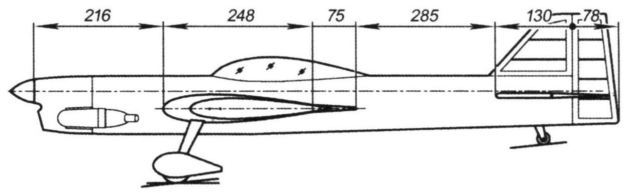
 Aerobatics cord models is equally good as sport, as a fun hobby. It is not surprising that interest in this type of modeling remains in the world until now, not to say followers of radiopilot. Design cord models evolving, gaining new and new features. Today, we give drawings and a description of the car created in accordance with the latest requirements of flight “fashion”.
The model is developed under relatively heavy engine working volume of 6.5 cm3. It could be MDS or other motor of similar capacity and design. If the carb is made in radiolarite, it will have to replace the decorative cap standard aerobatic shtorkoj. For ease of installation the fuel tank need to hold the nozzle through new holes drilled in the forward pipe of the crankcase of the engine together with futorki (as shown in the picture of the fuselage). In the case of use of the engine with the crankshaft mounted on bearings, it is possible to lengthen the forward fuselage by about 30 to 40 mm and use the engine cubic capacity increased. For this model well suited, for example, O. S. MAX-40LA, up-to -46LA, displacement 6,5 – 7,6 cm3. For these engines is characterized by the ability to work in pseudocatenulatum mode while maintaining high power and relatively low fuel consumption.
The construction of the model should start with the wing and stabilizer, as they are in the Assembly “pilotage” ready embedded in the fuselage. Their design and production technology is quite traditional and should not cause difficulties. So that when gluing the frame to eliminate any distortions, under the rear edge of the wing need to enclose the rake of variable height so as to align all of the ribs are parallel to the mounting plane. In General, for all the work on the wings and tail surfaces it is important to remember that these elements should be smooth and symmetrical. Therefore, all measures to ensure and control the accuracy of Assembly is justified.
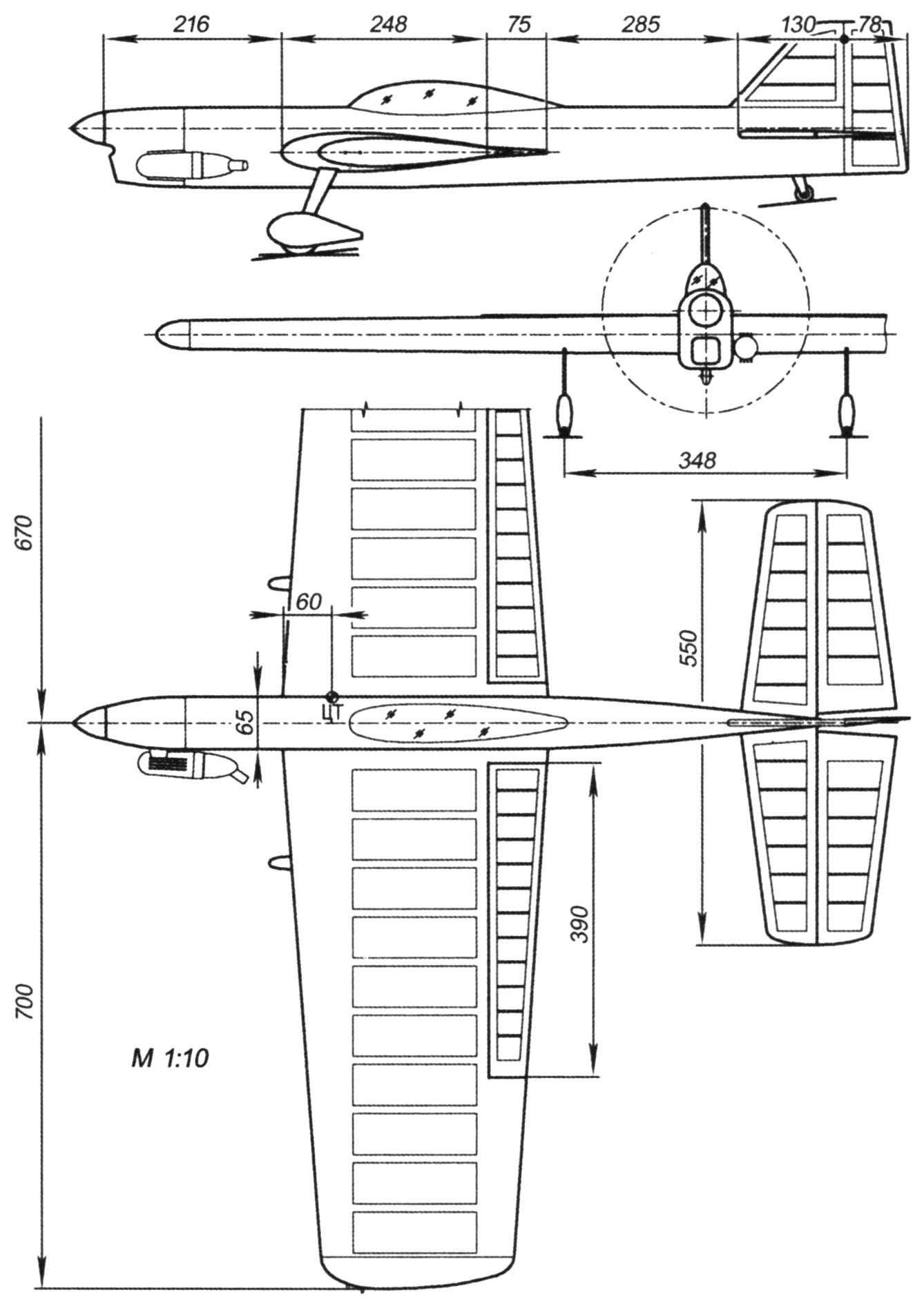
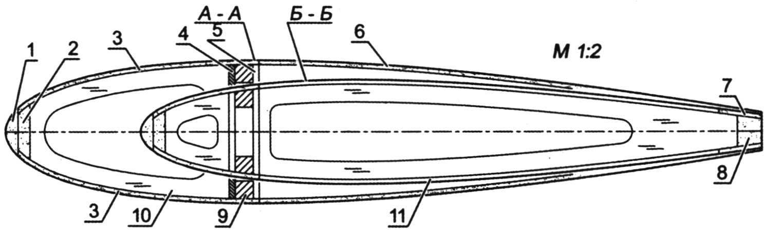
Flight model F-2-“Sirius”
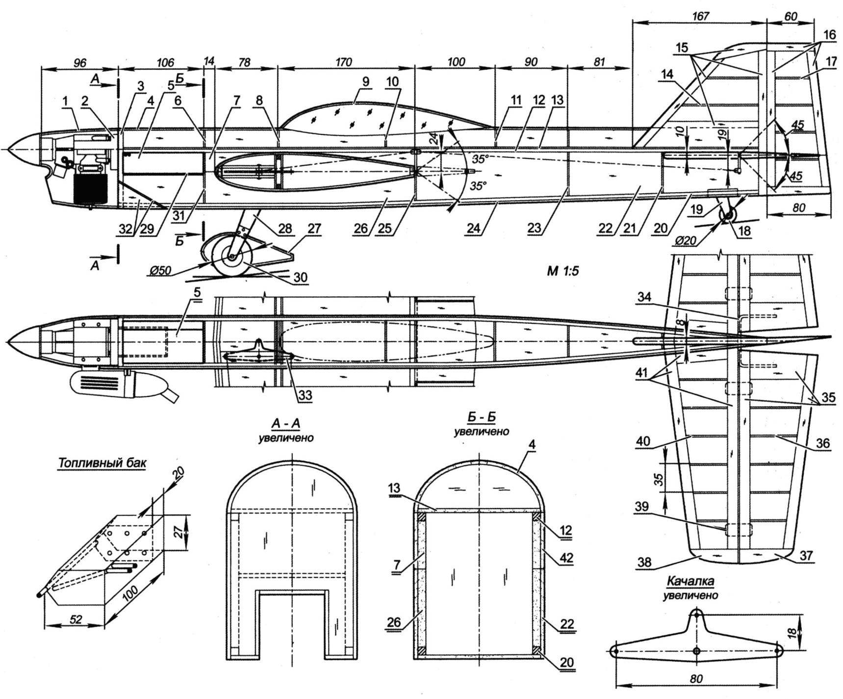
Fuselage:
1 – the engine cowling (GRP, s1); 2 — motor; 3 – front frame (plywood of five layers of plywood s1); 4 – skin of the fairing (balsa s2); 5 – fuel tank (sheet s0,3); 6, 8, 10, 11 – frames fairing (balsa s2); 7,26 – reinforcing pad (balsa s4); 9 – the canopy (plexiglass s1); 12 – upper longeron of the fuselage (pine 4×4); 13 – upper fuselage (balsa s2); 14 – rib keel (balsa s2); 15 – frame keel (balsa s8); 16 – frame rudder (balsa s8); 17 – the rib of the rudder (balsa s2); 18 – the tail wheel; 19 – stand (D16T sheet s1,5); 20 – the bottom longeron of the fuselage (pine 4×4); 21, 23, 25 frames (balsa s3); 22,42 – Board (balsa s3); 24 – lower valance (balsa s2); 27 – the spinner wheels (polystyrene, ABC-plastic or fiberglass s1); 28 – landing gear (sheet D16T s3); 29 – the wall (balsa s2); 30 – wheel; 31 – frame (plywood s2); 32 – the covering of the channel for the air outlet (balsa s2); 33 rocking (sheet D16T s3); 34 – torsion (wire OVS Ø2. 5); 35 – frame rudder (balsa s10); 36 – rib rudder (balsa s2); 37, 38 – ending (balsa s10); 39 – loop; 40 – rib stabilizer (balsa s2); 41 – frame stabilizer (balsa s10).
The picture shows the limit angles of deflection of the rudders
Before covering the lower part of the sock don’t forget to force the ribs to attach the landing gear. The main control unit subsequently no longer available, checked for smooth operation and no backlash. All rubbing parts is useful to lubricate with grease. The only thing left then is the installation of rear center section of the wing and the torsion of the drive units of the flaps and elevators. These details are put into place only after complete Assembly of the model before gluing the bottom skin of the fuselage. Of course, rudders and flaps are also hung later.
The fuselage in the manufacture of enhanced pads made of balsa 4 mm thick, extending from its front edge until the rear edge of the wing. Both sides are glued the side walls are made from pine slats with a cross-section of 4×4 mm. the Next step – a joint installation of the sidewalls and frames. Received by the node, in turn, is glued to the upper flat panels of the fuselage, pressed at this time to Board the slipway. After drying of glue, you can begin to assemble the top gargrota fuselage (by the way, with this design the entire fairing, in fact, has a purely decorative function). Lower the trim panel is put in place only after the binding engine, tank, mounting the wing, stabilizer and debugging the entire control system. Pre-assembled the vertical tail is glued in the design of the fairing. In addition, it is necessary before closing the fuselage bottom don’t forget about the exit channel of the cooling air engine and a plywood plate that reinforces the bottom wall of the fuselage in the reception area of the tail wheel. Also will not be superfluous to once again control the installation of the fuel tank at the height of its plane of symmetry must coincide with the level of the axis of the jet engine.
In the assembled fuselage using templates and profile while controlling the precision cut holes for the wing and stabilizer. Here is fully justified principle-measure twice, cut once. The fact that the quality of the Assembly will in large measure depend on all the basic flight characteristics of the model and the nature of its behavior on shapes. Under the shanks of the end portions of the wing may have to cut the sides of the fuselage of additional small grooves. It’s not terrible, as processing the slot with the excess overlap as yet unidentified shanks of center, holding at the same time the elbow tube torsion of the drive flap. If everything is in order, it is possible to mount themselves of the actuators of the rudders and flaps, as well as to hang all traction. Needless to say, it also requires a thorough inspection and adjustment of the entire control system.
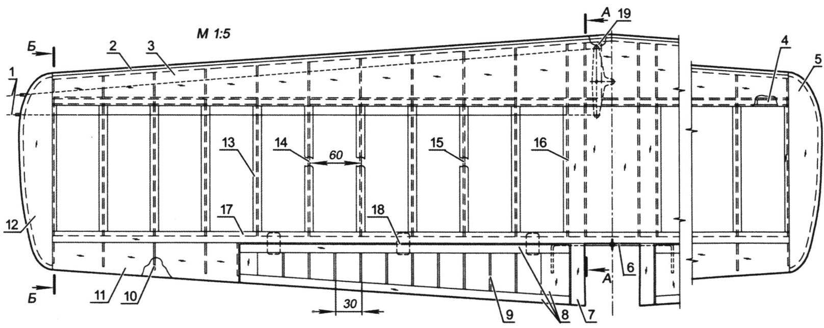
Wing:
1 – thrust rollers (OVS wire Ø0,8, or cables); 2 – pad front edge (balsa s4); 3 – skin of forehead (balsa s1,5); 4 – cargo (30 g); 5 – the right ending (balsa); 6 – torsion of the drive flap (OVS wire Ø2. 5); 7 – shank root of the wing (balsa); 8 – frame of the flap (balsa s10); 9 – rib flaps (balsa s2); 10 – rib of the shank end of the wing (balsa s2); 11 – casing of the shank end of the wing (balsa s1,5); 12 – the left ending (balsa); 13 – plate rib (balsa s1,5); 14 – rib (balsa s2); 15 – reinforced rib under the landing gear mount (plywood s2,5); 16 – the covering of the wing (balsa 1,5 s); 17 – trim the trailing edge (balsa s1,5); 18 – loop; 19 – Planck-axis rocking (plywood s3, 2 PCs.)
The wing profiles:
1 – pad edge (balsa s4); 2 – edge (balsa s4); 3 – skin of forehead (balsa s1,5); 4 – Central wall (plywood s2); 5 – wall of the spar (balsa s2); 6 – covering of the wing (balsa 1.5); 7 – trim edges (balsa s1,5); 8 – trailing edge (balsa s8); 9 – shelf (pine 6×6); 10 – rib (balsa s2); 11 – shelf rib (balsa s1,5)
Section match the pattern “Wing”
The joint of the first frame with the fuselage, it is desirable to paste a strip of thin fiberglass and wrap wide adhesive tape. After curing, epoxy adhesive tape is removed, and the surface of the connection practically will not require any putty. The lantern is embossed hot out of the transparent plastic sheet about 1 mm thick, is fitted to the fuselage and glued in place after the cockpit. Regarding the granularity of the cabin equipment no we do not give advice, because it all depends on personal preferences and capabilities of the manufacturer of pilotage.
The engine hood is best applied to the wall of the fiberglass epoxy resin. In extreme cases, allowable to pull it out of heat resistant abs plastic. The use of polystyrene is not desirable. Due to the heat of the engine and compressed shape of the hood possible deformation of this part.
To fit model is the easiest wrap type Monocote color main background finish, with subsequent application of decorative elements toplivostojkaja paints or other film colors.
Flight model F-2-“Sirius”
The displacement of the engine… 6.5 cm3
The mass of the model………………….1350 g
Wing area………………..38,2 DM2
Propeller……………..280×127 mm
V. ZAMOLODCHIKOV, master of sports, St. Petersburg
Recommend to read
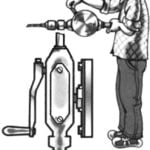 TO DRILL THE FLYWHEEL?
Drilling steel mechanical hand drill even in the upright position without special tools is not easy: need and pressure to create, and perpendicular to endure. What if you set one of the... AMPHIBIAN AMPHIBIED
It’s tempting, isn’t it, to leave your house on a velomobile, get to the nearest body of water and, rolling down from a low bank, continue moving along the water? This will become possible...
