The main element of the wing is a single Central node, consisting of team strength rib-reinforced plates monolinuron and an attached oblique polonorum with elements of the longitudinal set. In the manufacture of finished parts you need to keep in mind that mostly they are processed in the stack, and the spar is part of them in round drilled holes, through which are held in the filing, and screws, tightening the pack. It is also useful to note that at the stage of preparation of parts is the easiest way to produce a partial profile of the ribs (completely profiled only the forehead and a straight area of the tail) to finish it after the wing Assembly. Installation of parts into a single frame on a flat bench, using epoxy resin. Other binders are not used, as the joints a bit, and they are all intense and very important.
Fig. 2. The fuselage Assembly from the tail boom:
1 — pad (aluminum 3 mm), 2 — base (gluing two sheets of plywood 3 mm thick), 3 — bow cleat (plywood thickness of 3 mm), 4 — balancing ballast (lead shot), 5 — filler (foam thickness 6 mm), 6 — Logement trim (beech rail cross-section 4×7 mm), 7 — axis screw wing mounting, 8 — hole 0 1.5 mm thread under the firmware area of the screw that protects the plywood from cracking 9 — pin fixation wing (bamboo rake 0 2 mm), 10 — round detachable tail boom (rack of grained pine with a cross section of 6×6 mm, smoothly utonchennaya to the tail to 2,5×6 mm), 11 — thread proshivka of the keel and crutch to the fuselage (to spill glue), 12 — covering the front part of the keel (Whatman) 13 flange (of pine raked a cross section of 3×4 mm), 14 Kil (melkosortnyj the foam thickness 3…4 mm), 15 — filament proshivka the stabilizer (shed glue), 16 — the crutch (the wire OVS 0 0.8 mm), 17 — shear the coil mounting beams, 18 —wheel (plywood), 19 — copper rivet 0 3 mm. fuselage Assembly is to epoxy glue.
Fig. 3. Wing:
1 — ending (melkosortnyj foam with pasting a strip of thin paper on the PVA glue), 2 — intermediate Polonnaruwa (melkosortnyj the foam thickness 3…4 mm with taping the ends of a strip of Whatman), 3 — power Polonnaruwa (plate of thick basswood, 3 mm thick), 4 — front edge (pine raked a cross section of 3×4 mm; to reach through the hole 0 4 mm in the metal sheet), 5 — spar “abalone” (pine rail section 2,2×7 mm; in the ending of glue in the groove), 6 — reinforcement of the joint edges (wire winding of thread and glue), 7 — rib (plate of crisp lime with a thickness of 3 mm), 8 — spar wing (raked from dense grained pine with cross section of 6×6 mm), 9 — Central oblique Polonnaruwa (plate of lime thickness 2.2 mm), 10 — strengthening of the wing (plywood thickness 1mm top and bottom), 11 — power trim Central rib (beech or birch, plate thickness 3 mm), 12 — power of the Central rib (Linden or beech, plate thickness 8 mm), 13 — shank, the Central ribs (a plate of crisp lime with a thickness of 3 mm), 14 — back edge (pine rail cross section 2×6 mm), 15 — strengthening edge (pine rail section 2×3), 16 —strengthening of the junction of the trailing edge (wire winding of thread and glue), 17 — oblique Polonnaruwa (plate of lime with a thickness of 2.2 mm; if desired, the junction with the children. 3 enhanced plates-kerchiefs of paper or veneer), 18 — the screw of fastening of the wing to the fuselage (screw 3×35 mm), 19 — firmware prone to cracking zone threads with glue, a 20 — square scarf (lime), 21 — the firmware of the intersection of longitudinal threads with glue.
Wing Assembly is done on epoxy glue.
Fig. 4. The profile of the wing and marking grooves under the frame members.
Fig. 5. Finished the wing elements:
A Central oblique polonaruwa, B — oblique polonaruwa. In the rib joint of the “lug” with the center section.
Fig. 6. Stabilizer:
1 — wedge-shaped insert edge (Linden), 2 — front edge (pine raked a cross section of 3×4 mm), 3 — double-sided pasting of the Central zone of the stabilizer flipcharts, 4 — stabilizer (melkosortnyj the foam thickness 3…4 mm).
Wing after polishing is to be bound long-fibre paper or thin Mylar film by a known technology. In the case of a film of plating is possible at the upper edge of the rib of the transition center at the “eye” to saw through the groove widths of 0.6— 0.8 mm, to subsequently using nylon fishing line to pull the film in the most difficult of the stitched area. In addition, if you want valid with the lower part of the profile in minervarya sections to glue the covering to the spar. The result is some semblance of a concave-convex profile, which improves load-bearing properties of the whole wing.
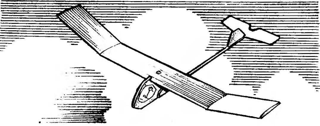
The fuselage design is simple and does not require special explanation. The only thing would like to stop the attention — detachable attachment of the tail boom. Best joint rail-beams with shanks dural side overlays wrap the threads with a minimal amount of glue. In this case, the strength of the connection meets all the requirements of reliability, and in case of accident to replace the I-beam will be more than just that. Similarly designed and empennage: for all its reliability in case of breakdowns easier not to repair the foam elements and cut and paste destroyed in their place newly made.
The side of the fuselage in the area of “cockpit” can be covered with a thin paper and put a picture reproducing equipment, instruments, control stick and pilot’s. Painting model — the taste of the manufacturer. It should be noted that the weight of the airframe reserves are very large and the decoration can not save.
Recommend to read FUEL TANK — CO2 Whatever you say, but the popularity of a particular model often depends not on its flight data and... flight readiness. That is why many modelers prefer to equip their technique is... Horned adjustable This upgraded wrench I use for many years and I think it is very convenient. Drill a hole and his lips pressed to two steel pins, I was a versatile tool to unscrew and also hidden castle...