
 Increasingly, we receive letters from readers describing flying models, which instead of internal combustion engines operate motors of different systems. This is quite natural and timely: judging by many indications, the electrification of aircraft modeling – in sight. No wonder the first successful examples of flying models are available in the “toy” version of some foreign model aircraft firms. Among them are low-cost models, capable of conducting free uncontrollable flight duration of 1-3 minutes, Cordoba for the different types of food on the wire and even radio-controlled model of the coast, including the piloting. The duration of the last flight without recharging has managed to bring up to 10-15 minutes. However, the electric power is still inferior to compression and heat rating.
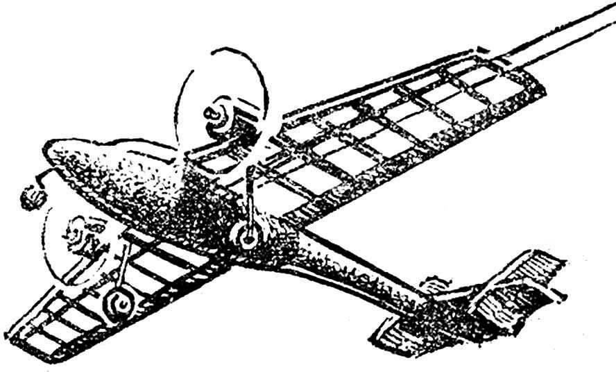
Our magazine has described the constructions of models with electric motors of domestic production. Today we put the description of another cord twin-engine models with DP12-A engines built GI Nesterenko from Zaporozhye.
This model is intended as a demonstration for the flight in a camp, children’s festivals, gatherings of young technicians, especially when it is important to show the rapid preparation for the start, reliable start-up, precise execution of the program.
Selection of a twin-engine scheme is explained by the desire to obtain a higher thrust-weight ratio compared to single-engine (with the same engines), as well as to achieve a more stable and reliable outdoor flight.
Model drawing in which three projections depicted in Figure 2, is constructed entirely of plastic foam PS-1. All connections are made with thick casein glue (frame, load-bearing elements) and glue PVA of varying thickness (foam taping pieces of paper). With this technology failed to achieve high weights of culture (model glider without motor weighs about 50 g, gross weight – about 130 g). The frame of the wing (Fig. 1) is made of 1 mm thick plywood (spar) and lath pine 3X4 mm section (rear edge). Ribs – lime of the veneer thickness of 1 mm or more rigid foam of the same thickness. Cording – capacitor paper.
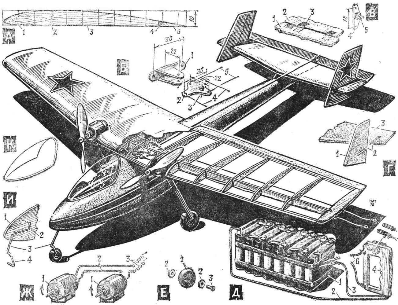
Fig. 1. The overall layout of twin-engine models with electric motors:
A – 1 wing rib – spout (foam) 2 – spar (1 mm thick plywood), 3 – an edge rib (veneer, plywood, thickness 1 mm), 4 – edge 5 pine – tail (foam); B – the central rocking design: 1 – Front, 2 – Phillips rocking Micarta or Plexiglas, 3 – the plug rocking chair (stick), 4 – tokonositeli Cordes, 5 – nylon filament to the handlebar height; In the elevator and its suspension: 1 – regulator, 2 – elevator, 3 – silk ribbons that serve as hinges, 4 – hog 5 – Regiment pig; the T – connection with the horizontal tail keels: 1 – keel, 2 – connecting grooves 3 – the stabilizer; D – power supply and its connection with the model of the control knob: 1 – 8 unit of 3336L Battery, 2 – a direct line to the handle, 3 – wire with clamp, 4 – Handle 5 – Power switch 6 – tokonosnteli-cords; E – wheel chassis design: 1 – disk of foam or sponge rubber, 2 – washers made of plywood 1 mm thick, 3 – the plug (aluminum rivet Ø 4 mm); F – Engine wiring diagram: 1 – engines 2 – hard wire between the engines, 3 – twisted wires connect to the rocking chair; And – construction of the nose landing gear: 1 – plywood stiffener 1.5-2 mm thick, pasted into the fuselage, 2 – curved chassis leg, thread sewn with glue to the ribs 3 – rack, 4 – fork of the front wheel; K. – lantern cockpit, squeezed out of the film or plexiglass no more than 1 mm thick.
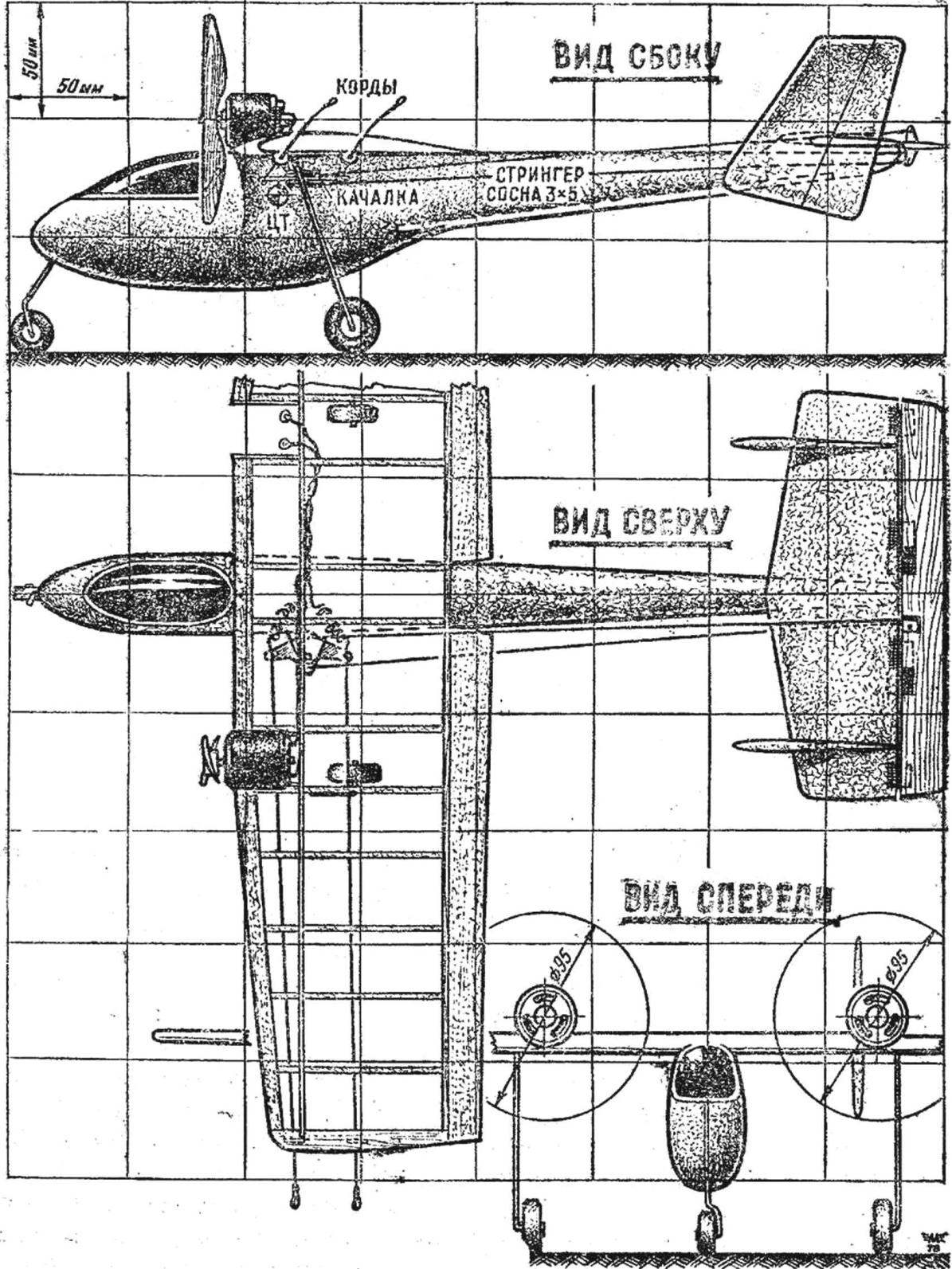
Fig. 2. Scheme of the model in three dimensions and the individual design elements.
The fuselage and tail parts – entirely from foam. Inside the fuselage to be hollowed to reduce weight. The wall thickness of the remaining variable – 6.8 mm from the lower (bottom) part 3-4 mm and the upper side. The underside of the tail boom, as shown in the diagram, power glued pine stringer section 2,5X2,5 mm. In the bow – plywood stiffener thickness of 2 mm for attaching landing gear. Racks are made of steel piano wire Ø 1.2 mm foam wheels on both sides of papered washers 1 mm thick plywood.
In general, the construction of the airframe is not difficult, this work can easily cope model airplane builder secondary qualifications.
Finalization of electric motors is carried out in this order. First you need to remove the back cover, on which the terminal and brush. The factory is tightly bonded to the body, so you need to use a sharp knife or scalpel, to cover after assembly of the village to its place firmly, without distortions. Case and cover are made of brittle plastic, so the work should be carried out very carefully.
Pulling the anchor in the motor housing cover and cut out holes for the cooling in accordance with Figure 3. Then it is necessary to thoroughly clean the inside of the cavity to collect sawdust and detail, paying particular attention to the fact that the anchor is easily rotated. After that, the lid can be glued into place (dichloroethane or glue BF-2).
Ready engines mounted on a wing model, as shown on Figure 2, and the thread is securely fixed with glue. Electrical connection of motors any. Depending on the switching rotation may be provided in one or opposite directions. It is advisable to make a connection so that both the shaft rotate clockwise when viewed from the front of the model. In this reaction screw rotation direction will contribute to a better flight in a circle pattern. In addition, the manufacture of two identical air screws easier. Secure the screws on the shaft tight fit with glue BF-2 (the easiest way) or via chiseled metal sleeve and the locking screw (more reliable and convenient to replace the screws).
As the cord for piloting applied electric wire marks PEL-section of 0.3 mm and a length of 5 to 7 m (depending on flight conditions). Electrical and aerodynamic resistance of the cord is small.
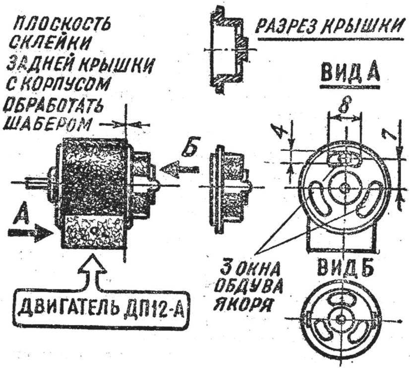
Fig. 3. Further development of motor DP12-A for its installation on the model.
Fig. 4. The drawing of the propeller.
To supply the engines collect a block of 8 3336L batteries connected in series. One conclusion from the unit is connected directly to the Korda via control knob (Figure 1 A, A) and the other wire should be at the end of the “crocodile” or kakoy-libo other clamp for connecting different numbers of batteries (at the start – no more than 6, and then – at least the fall of the container and consequently reducing the motor speed to connect additional battery circuit). Experience has shown that the kit is enough for 6 flights at 5 min, ie, in total – 30 min flight. Of course, 3336L battery – not the best source of supply for this model due to the relatively small capacity; much more advantageous to use block elements “Saturn” or the motorcycle type batteries, however, the entire plant is inevitably more cumbersome.
Selection of screw and quality of its production for this model are of great importance. Since the thrust engine used is small (about 20 g per booth at 4000-5000 rev / min), even a slight loss it will be very noticeable. Several Of the screws made me the best results the picture shown in Figure 4. The material is lightweight basswood. The surface of The blades must be carefully processed and polished to a mirror finish. Weight is well made screws should not exceed 2.5 g
If the constructed model is made in accordance with the stated requirements in this specification, it will be very effective to fly, although with a lesser rate than the model with piston engines. This allows you to see her better, and when combined with quiet operation makes it particularly beautiful flight.
G. Nesterenko, Design Engineer
Recommend to read
 COSTUMES FOR SURFER
Applied the last stroke of paint on the Board-float; the number sewn to the sail, varnished mast and you start thinking about the first release in the "open sea". But, before you do... PROFILE -UNIVERSAL
As you know, W-shaped plastic, wooden or metal profile furniture used as a guide slider for sliding glass doors. However, these profiles may well be used as shelf supports in cabinets...
