The hull of a sailboat is fairly simple, so the constructor of ship models can choose any technology of its production. In particular, it is possible to do a stacked body with a shell of mm plywood, you can cut a billet of foam and paste over it with a thin fiberglass using epoxy resin. It also proposed a matrix method, which can be used to replicate the hull, creating a fleet of boats with hulls with monotypes.
The first stage is the fabrication of the master model, or, as it is dissonant-called experts, fool. This will suit almost any materials, but the easiest way to do the Central building of the pair of plates of the sidewall thickness of 10-15 mm and a plywood bottom and decks. Side floats — lime bricks.
After docking all three elements of the master model puttied carefully skurida and painted with several layers of nitroenamels with intermediate grinding. Ready master model is covered with a release layer (e.g., two or three layers of wax parquet putty with careful polishing).
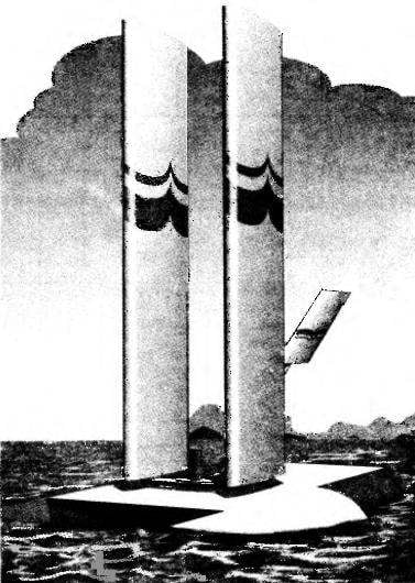
Model sailing ship class “P” with swivel-sail system:
1 — the sail-wing; 2 — knot sailing system, articulated; 3 — keel (plywood s5); 4 — housing; 5 — feather of a steering; 6— sail-stabilizer; 7 — M6 screw mounting sails-stabilizer; 8 — nut M5 mounting hinge Assembly; 9 — cross member.
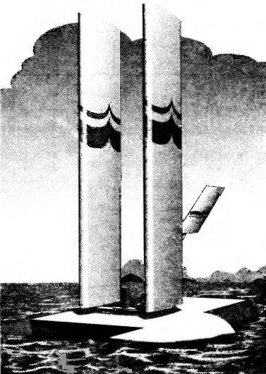
The position of the sail-wings b sails-stabilizer in various courses:
A — in the course of a close-hauled port-tack; B — on the course before the wind; In — course close-hauled starboard tack.
Table control sections profile, sail-wing
The sail-wing:
1,8 — ending (plywood s3); 2 scarves (Linden s3); 3 — bushing screw, connecting (aluminum, pipe 8×2); 4 — flange front (pine, rail 14×8); 5 — mast-spars (pine, rail 20×6); 6 — rib (Linden, plate s2); 7 — flange back (Linden, rake 22×8).
Hinge joint sailing system:
1 — nut M5 mounting hinge Assembly; 2 — bushing, hinge (aluminum); 3 — roller hinge Assembly (steel); 4 — crossbar housing (pine, rail 50×20); 5 — washer (steel); 6 — screw M6; 7 — traverse (aluminum, sheet d5); 8 — rivet (aluminum, d3, 2); 9 — beam spar (pine, rail d12); 10 — cross member (dural needle d3); 11 — sail is a wing; 12 — M6 screws of fastening of the sail-wing; 13 — bushing screw, connecting.
The sail-fin:
1,6 — ending (Linden, plate s3); 2,5 — rib (Linden, plate s1,5); 3 — edge front (pine, rail 5×4); 4 — spar (pine, rack of variable cross section); 7 — solitaire (Linden); 8 — flange rear (lime, rake 10×5); 9 — adapter (wire OVS d3).
The next operation — making matrix. First, the lower part of the hull (without deck) glued a couple layers of thin fiberglass using as a binder an epoxy resin. The first layer is carefully pressed against the surface of jerk between him and the fiberglass should not be air bubbles and excess resin.
After polymerization of the resin composition is prepared from normal river sand and of the same “epoxy”. The resulting mass is laid in a wooden box, whose dimensions slightly exceed the dimensions of the enclosure, and then up to deck level “dives” the master model with preformula-tion to her shell of fiberglass. Epoxy-sand composition is compacted by carefully tapping on the box and the surface of the mass is aligned flush with the deck level of the hull. The next day the master model carefully extracted from the body — the matrix is ready.
Now take up the actual production of housing. The inner surface of the matrix by the already familiar technology is covered with a release layer, whereupon it is applied to the front layer of the future shell case — tinted nitro epoxy resin. Without waiting for complete curing of this layer (the resin should still be sticky), inner surface of the die is glued with fiberglass (3-5 layers depending on tissue thickness), and the first layer of the most thin fabric privorovyvat to the matrix carefully. Carefully fit the fabric into the corners (edges) of the case.
After polymerization, the epoxy resin body shell is removed from the die and it cut the holes for rudders and keels. Further, the housing is glued cross of pine boards 20 mm thick, designed for fastening it to the hinge Assembly dvuhyarusnaya system.
The thus-prepared shell is embedded in the matrix, on top of her stretched plastic film and cover made of 10 mm plywood with nasverlennye holes in it. Their diameter is chosen such that through holes can be put the nozzle of the spray foam — it fills the internal volume of the housing. For this cover using the clamps pressed against the matrix, and fitting the spray is introduced sequentially into the openings. The separation of the foam from the holes means the end of the process of filling her body.
A day later, when the foam will turn into foam, the hull is extracted from the matrix and fixed-cut from plywood plates keels and rudder blades and the deck.
Hard sails (wings) are made in exactly the same way as the wings of the aircraft. Each of the wings is collected from a pine side rail (rail 20×6 mm), ribs cut out of fake plates with a thickness of 2 mm, two plywood (thickness
3 mm) endings, as well as the pine of the front and rear edges. In each of the ribs is provided an oval hole in the spar at the locations of ribs arranged slots. During Assembly of the wing, each rib onto the spar, be brought up intended for her slot, is rotated 90 degrees and thereby firmly fixed to the spar.
For Assembly of the wing makes sense to make a simple staple consisting of a flat Board, to which are nailed the rail that supports the rear edge. Its thickness is chosen such that the plane of the chord of the wing was parallel to the plane of the Board-pile. Wing Assembly is conducted with the help of epoxy glue.
In the lower part of each wing cuts the dural tube diameter 8×2 mm, in which the length of 30 mm is threaded MB. This detail is attached to the spar with epoxy glue with increased adhesive bonding by winding a nylon thread impregnated with the same adhesive.
At the top of the longerons drilled holes with a diameter of 3 mm, intended for fixation in them of the cross of dural knitting needles, connecting the upper part of the wings.
Both sails wing-fixed 6-mm hexagon socket screws on the hinge node, consisting of dural yokes with riveted thereto a hinge sleeve.
Counterpart of the hinge is a stepped roller at the upper end of which the shank with thread M5, and on the bottom made rolling. Mount cushion in a pine cross member of the housing with epoxy glue.
In addition to the wings on the hinge node stabilizer is attached, with which the wings are set at an optimum angle to the wind direction. The stabilizer consists of pine beams-longitudinal front and rear edges, a pair of wingtips and two ribs of fake plates.
The side rail is a rail with variable section in its rear part on a length of 250 mm square cross section 8×8 mm, rolling in the next round with a diameter of 12 mm. Mount I-beam of the spar to the hinge node using the adapter, bent from a steel wire in diameter of 3 mm, which in a beam-longitudinal longitudinal drilled hole 3 mm in diameter; locking of parts with epoxy glue. In the dock area beam spar wrapped with nylon thread and subsequent impregnation “epoxy”.
Before you start you need to install sails-wings so that the plane of the chords were parallel to each other, and the angle between the planes of the chords of the sails of the stabilizer and the sail-wing was 3-5 degrees. More accurately, this angle can be determined in the process of trial starts. Note that when you change the tack of the sail position of the stabilizer relative to the sail-wing is changed to a mirror-symmetrical, as can be seen from figure on p. 26 (A and b).
Full courses close to the wind (when the wind is blowing from behind or from the rear side), you need to deploy a hinge joint stabilizer forward, and the wings-sails set, “butterfly”.
I. TEREKHOV
Recommend to read IL-18 Four-passenger aircraft Il-18 was designed at OKB Ilyushin in 1956 4 July 1957 the prototype it with TVD NK-4 first took to the sky. It was designed to carry 75 passengers. In October of... THE SWING OF THE EARTH… AND WATER In any courtyard you can see the beds, the game elements of children's playgrounds made of old tires. On the river boats and the wharves they are used as fenders. But this is not all...