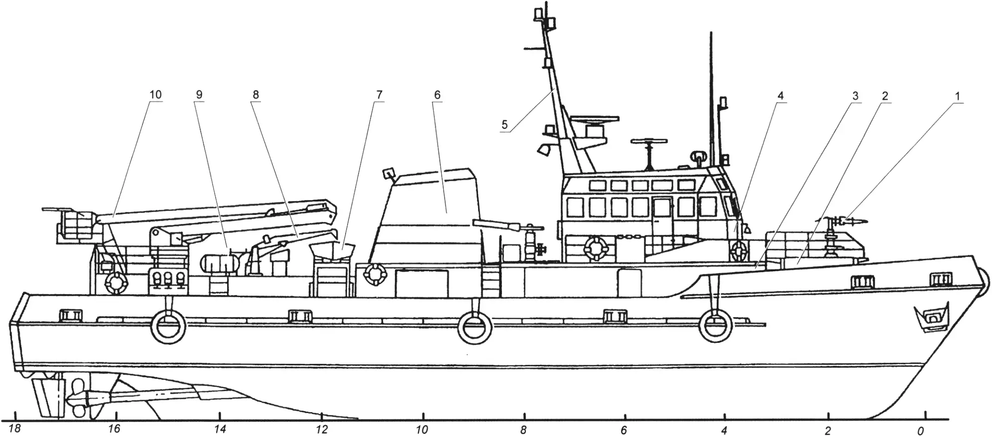
Vessels of this class can be found in all major ports of virtually every country in the world. These are rescue craft built to assist those in distress, fight fires, patch hull damage, pump water out of flooded compartments, refloat grounded ships, and tow them. They differ in displacement, speed, and technical capabilities. A large group among them consists of fire-rescue boats. One such boat served as the prototype for this model, built to a scale of 1:33.
The fire-rescue boat is a twin-screw vessel with a superstructure and a wheelhouse, fitted with a lifting gear in the stern. Length — 36.2 m, beam — 7.57 m. The power plant consists of two diesel engines of 900 hp each, driving propellers 1.65 m in diameter; the boat’s speed is about 14 knots. For firefighting it is equipped with fixed fire monitors for delivering water and foam, located on the superstructure and on the lifting gear.
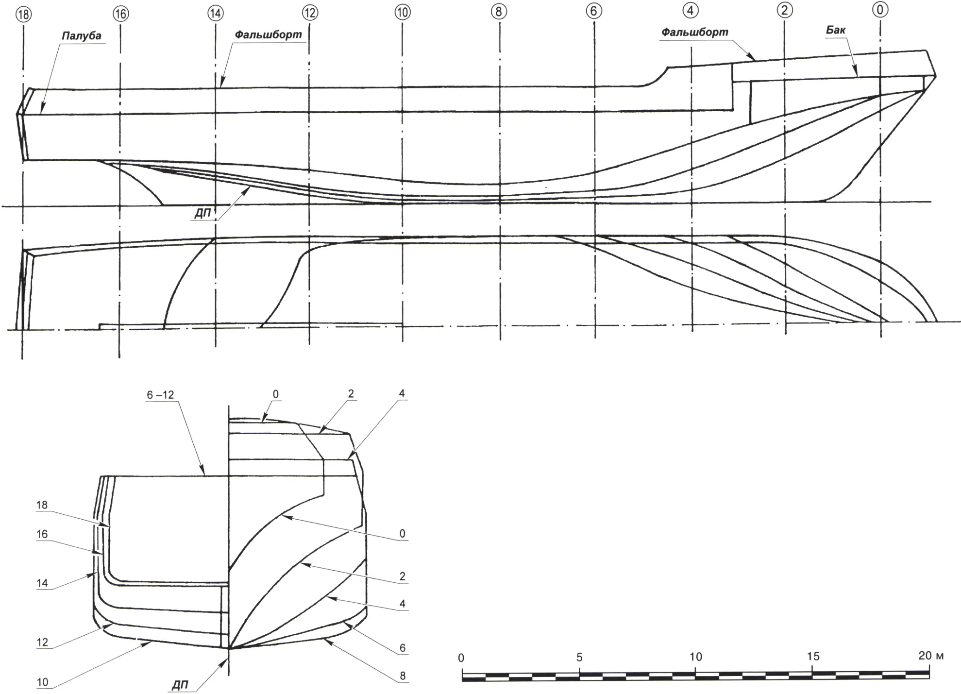
The model hull is best molded on a plug from epoxy resin and fiberglass cloth. To make the plug, you need to build a kind of “skeleton”: cut frames from thin plywood or cardboard according to the lines drawing and mount them on a straight long “backbone” stick. (Note that on the lines drawing the hull sections are shown to the outer moldings, so when making the frames their contour must be reduced by the thickness of the fiberglass shell.) Next, foam blanks are cut and glued between the frames. Excess material is removed to match the contours of the adjacent frames. Foam is worked with sharply honed tools — knife-planes and miniature planes. Flexible strips of plywood or polystyrene can be used to check the shape: by laying them against adjacent frames, it is easy to spot uneven areas on curved surfaces. Final finishing of the plug should be done with sandpaper glued to plywood strips and small blocks with surfaces of suitable curvature. If necessary, the plug is filled; this is easiest with ordinary modeling clay.
The finished plug is coated with a wax release compound and carefully polished so as not to crush the soft foam. A good covering can also be made from the thinnest food wrap, which does not stick to the epoxy binder. Depending on the thickness of the fiberglass cloth, four to six layers of this material will be needed to lay up the shell. Mold the hull in a well-ventilated room! After the epoxy has cured, the hull is sanded and trimmed along the bulwark line. Scuppers and openings for bitts are cut in the bulwark.
The deck is made of 5-mm plywood. Openings for the superstructures are cut in it, after which a 25-mm-high coaming is glued in. The deck is secured in the hull only after the motor, stern tubes, and steering gear have been installed.
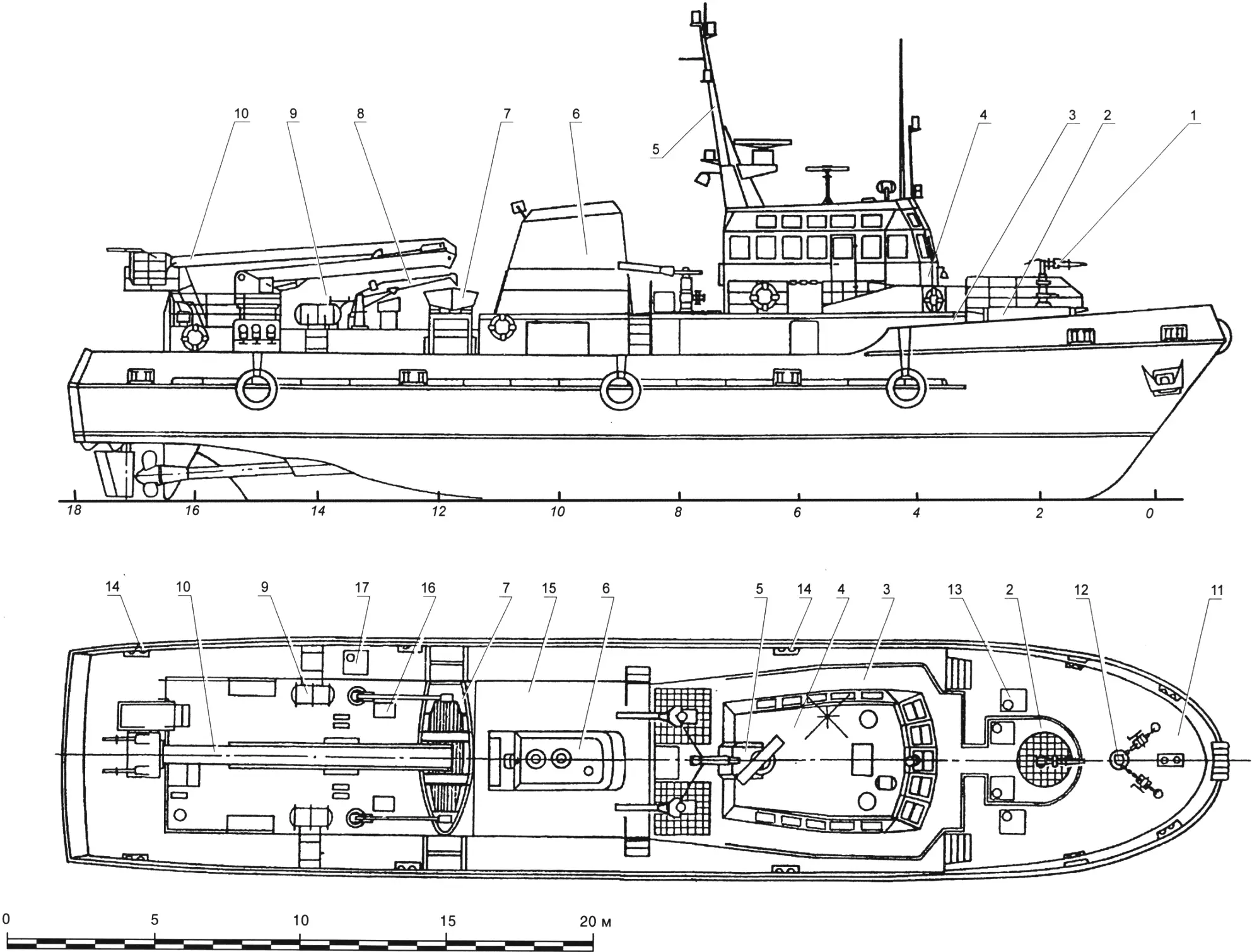
1 — forecastle fire monitor; 2 — forecastle fire monitor platform; 3 — wheelhouse superstructure; 4 — wheelhouse; 5 — mast with radar antenna; 6 — funnel; 7 — lifeboat; 8 — davit; 9 — life rafts; 10 — lifting gear with a working platform fitted with two fire monitors; 11 — forecastle; 12 — anchor and mooring gear; 13, 17 — hatches; 14 — bitts; 15 — engine-room casing; 16 — ventilation head
On the model’s forecastle are a platform with a fire monitor, mooring and towing bitts, hatches, and also the anchor and mooring gear consisting of a windlass, anchor chain, two stoppers, and two anchors. On the real vessel there are two ladders for descending from the forecastle to the deck; these must be reproduced on the model as well. Immediately abaft the forecastle on the main deck is a superstructure on which the wheelhouse is mounted, with two rows of windows around its perimeter. On the wheelhouse are fitted a mast with a radar antenna, a direction-finder antenna, whip antennas for radio sets, and a searchlight. Abaft the wheelhouse, two fire monitors are mounted on special pedestals.
On the roof of the engine-room casing is a funnel with angled sides. Abaft it, across the model hull, a boat and two davits are mounted on cradles. In the after part of the casing the lifting gear is installed. It consists of a rotating base, a telescopic boom, and a working platform on which two fire monitors are mounted.
The power plant is based on an MU-30 electric motor (voltage 27 V, current draw 5 A, speed 7500 rpm, power 40 W, mass 0.6 kg). Propeller drive uses a homemade gear reduction unit with a ratio of 1.33, which turns a pair of output shafts in opposite directions at 5625 rpm. Because most modelers have limited means for making gears, it makes sense to begin designing the gearbox by selecting a pair of ready-made identical gears with an outside diameter of about 30 mm and a module of 1.5–2 mm. From their geometric parameters the gearbox housing dimensions and design are calculated, after which a second gear pair is selected — its ratio should also be about 1.33.
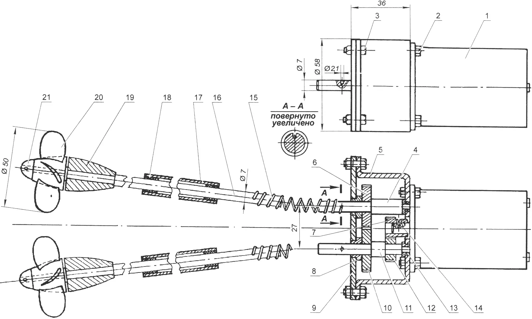
1 — MU-30 electric motor; 2 — gearbox mounting bolt; 3 — gearbox cover bolt; 4 — left gearbox output shaft; 5 — gearbox housing; 6, 10 — gears; 7 — primary gearbox pinion; 8 — bushing; 9 — gearbox housing cover; 11 — right gearbox output shaft; 12 — gear of the right shaft; 13 — small bushing; 14 — primary pinion setscrew; 15 — flexible spring coupling; 16 — propeller shaft; 17 — stern tube; 18 — textolite bushing; 19 — propeller-shaft bracket; 20 — propeller; 21 — fairing nut
The gearbox housing parts are made of 3-mm sheet steel and are joined by four bolts with nuts. The shafts are steel, turned; pinions and gears are press-fitted onto them, which provides quite reliable anti-rotation locking. The primary gearbox pinion is secured on the motor shaft by a setscrew with a conical tip. Bronze bushings pressed into the base and cover of the housing are used as plain bearings.
The motor together with the gearbox is mounted on a frame cut from 10-mm plywood and installed in the hull at 4.5 degrees to the vertical.
Propeller shafts 7 mm in diameter run in steel stern tubes in which textolite bushings are glued at both ends. During assembly the stern tubes are filled with grease. Built-up propellers, consisting of brass hubs with blades soldered to them, are 50 mm in diameter with a 24 mm pitch. Each is secured on the propeller shaft by a fairing nut.
Each propeller shaft and gearbox output shaft are connected by a flexible coupling in the form of a spring with an inside diameter of 7 mm, wound from 2-mm OBC wire. To prevent the shafts from slipping relative to the couplings, a blind hole 2.1 mm in diameter is drilled in each shaft, and hooks are bent at the ends of the spring.
The motor is powered by a 2KNB-2 battery pack with a total voltage of 25 V.
“Modelist-Konstruktor” No. 7’2025, Igor GALKIN
Recommend to read
 SWITCH FOR GROWTH
If necessary, almost any switch can be very simply converted so that they could be used by both adults and children. This will require a strong nylon thread and two balls of different... THE AIRCRAFT FOR THE CRUISER
We can safely say that the class of the ship ejection of seaplanes was the most short-lived in the history of Soviet aviation. There are many reasons, but chief among them is that in the...
