
 Ask any kid, building the first schematic model of what he wants Almost certainly he will answer — about copy. And it is clear. It’s no wonder it is believed that the replica model is one of the most interesting and complex classes of aircraft modeling. Order copies, model airplanes acquainted with the technical achievements of aviation, possess the perfect use of the tool.
The editors have received many letters asking to tell about the most simple and accessible variant of the retract chassis models-copies. We propose a scheme developed in aeromodelling circle Cut heavy machine tool plant in Kolomna. It is made on a model-copy aircraft An-24. Her designer Yuri Shabalin became the champion of the Moscow region and the silver prize-winner of all-Russian students competition in 1974.
The mechanism of cleaning and landing gear on the model-copy has the following requirements: the design must be simple and reliable in operation, it should contain fewer parts, to be light in weight to allow you to quickly replace parts that have failed during operation, and check them during routine inspections. Given these requirements, we built the model.
The mechanism of cleaning and the landing gear is as follows: microelectrochemical DP-10 through a reduction gear transmits the rotation of the drum. The cable is attached at one end to the lower part of the upper strut, the other end to the drum. Naratiwas on the drum, it pulls the lower part of the upper brace, which is connected pivotally with the bottom and therefore drags the main stand. Main landing gear in the retracted position is held by a taut rope. Intermediate suspension unit shall send the rope and reduces friction during movement. Top brace, describing an arc, thereby changes the angle of the cable cleaning between the point of mounting it in the upper strut to the movable block. As well as an intermediate unit is in the bearings, it moves with the rope, holding it in the groove and channeling in the connecting pipe leading to the working drum.
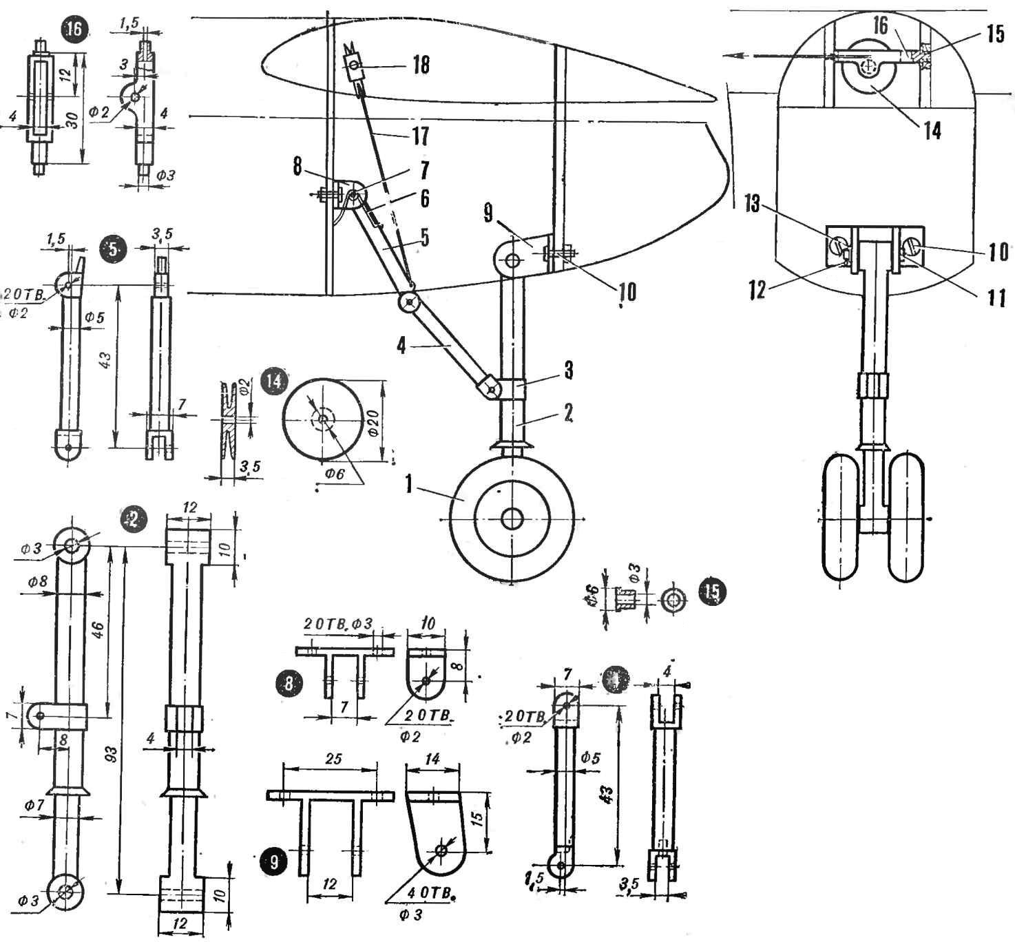
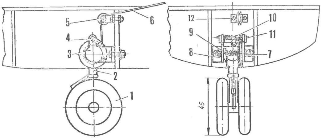
Fig. 1. The main Desk:
1 — wheel; 2 — chassis; 3 — lower eyelet; 4 — lower brace; 5 — upper strut; 6 — locking spring; 7 — axis spring retainer; 8 — headstock rear strut; 9 — headstock stand; 10 — bolt mounting bracket; 11 — the axis of rotation of the rack; 12— pin; 13 — washer; 14 — the block roller; 15— bearing; 16 — unit; 17 — rope of cleaning the Stoics, an 18 — unit.
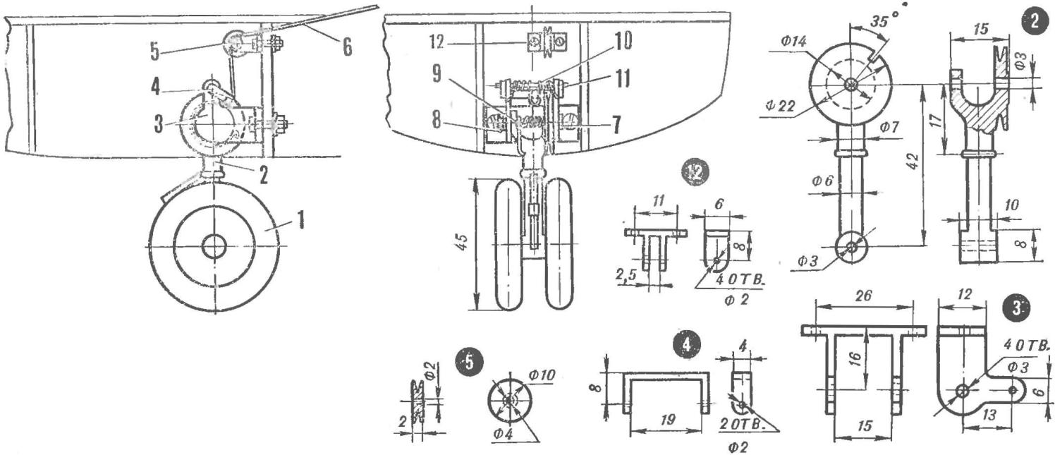
Fig. 2. Front:
1 — wheel; 2 — stoic, 3 — headstock stand; 4 — locking latch; 5 — intermediate; 6 — wire cleaning 7. — axle suspension strut; 8 pin; 9 — return spring; 10 — locking spring latch; 11 —axis of a hinge plate spring retainer.
The release of the main landing gear (Fig. 1) is carried out in the opposite direction. Releasing the tension on the cable, the steak with the recoil spring out of the nacelle and put on the face.
Cleaning the front steaks (Fig. 2) the chassis is as follows.
The cable one end is rigidly fixed ka drum of the main stand. Nativas drum gear, he removes from the groove (stop the bar) the locking latch and through the intermediate block clears the counter.
Release the a-pillar occurs in the opposite direction. Under the action of a return spring it goes, releasing the tension on the rope. Spring enters the latch roller in its slot.
All the details of the landing gear, except for the axles and the springs are made of duralumin D-16T.
When assembling and adjustment of the landing gear necessary to achieve alignment and free movement of all hinge connections.
The axis of the main parts of the landing gear can be quickly dismantled and troubleshoot.
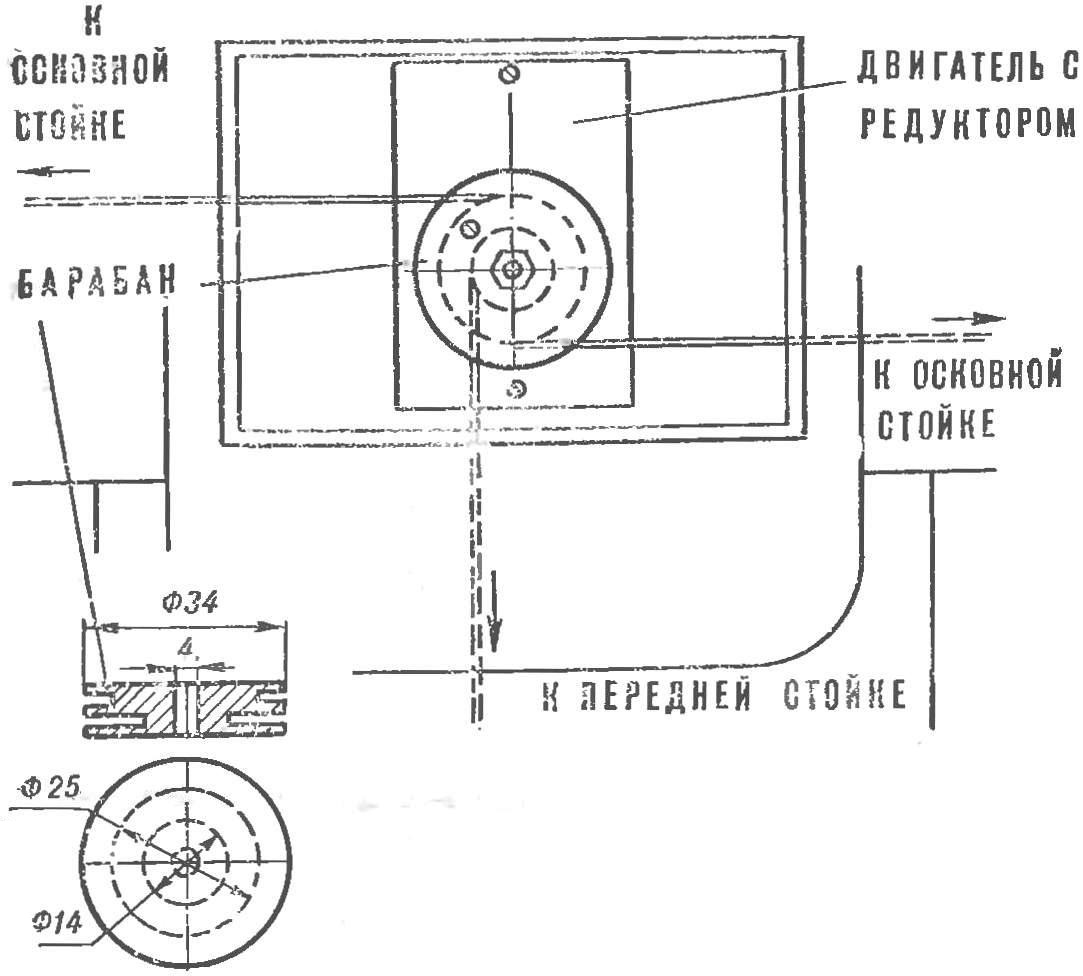
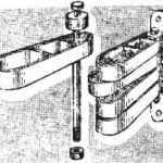
Fig. 3. The primary node of the mechanism of the retract chassis.
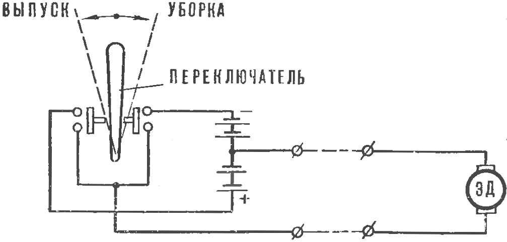
Fig. 4. A control scheme.
The control mechanism (Fig. 3) is located on the center at the junction of the wing to the fuselage. It is better to make removable, so you can rework or repair.
The control mechanism is electrical, it is a switch. The power to the actuators is supplied from two battery 3336L connected in series. They are about the pilot in the center of the circle. Current transmission is cable made of two wires, PELCO-0.25 and suspended to Kardam.
The wiring diagram of the control mechanism for a cleaning and landing gear-models Antonov An-24 is given in figure 4.
V. KLIMCHENKO, Y. SHABALIN
Recommend to read
 RACK SCREWS
There are various designs of towel racks in the kitchen or Kanna and. One of them is a vertical series of levers, threaded plastic end caps on the rod of the bracket, screwed to the...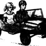 “JEEP” FOR THE TWINS
The "toy" industry is developing in exactly the same way as "adult", and tries to use it to create new and new designs of many of the achievements of modern science and technology. This...
