HIGH-SPEED ASYMMETRIC

HIGH-SPEED ASYMMETRIC

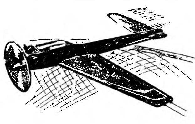
The proposed control line speed model (C. F2А) asymmetric scheme designed and built in the aeromodelling club “Falcon”, under the leadership of its founder and coach B. I. Shibanova, the 9th grader Alexander Fights. Personally on command by the primacy of Moscow in 1999 among young men, he took second place. His model showed speed 118,8 km/h. Structurally, the model replicates the appearance of speed with which athletes perform, including master of sport international class. Its features include an asymmetrical wing and stabilizer (actually halves of both), located on opposite sides of the fuselage.

In addition, the model is completely missing the keel and chassis as the structural elements, that impede the achievement of maximum flight speed.
 
The FUSELAGE is a flat, solid wood, made of Linden planks 9 mm thick sizes 380×45 mm. It has two cut length of 90 mm and a width corresponding to the thickness insert the wing and the stabilizer. Both of the cutout are parallel to the longitudinal axis of the model at a distance of 15 mm for the wing — from the lower line of the fuselage, and stabilizer from the top. The tail of the fuselage narrows. To give the best aerodynamic shape for the top of its edges and the tail part is rounded from the bottom, starting from the trailing edge of the wing. The entire fuselage is covered with fibreglass thickness of 0.03 mm, which gives it the necessary stiffness, and impregnated with varnish for painting.
 
For leash cord management system in the fuselage drilled two holes with a diameter of 2 mm: the first at a distance of 110 mm from the toe of the fuselage and the second in 36 mm from the first. From the bottom to the fuselage on the line of the bypass from the sock to the rear edge of the wing attached on the screws wpoty landing ski of duralumin plate with a thickness of 1 mm. It protects the model from damage when landing on the asphalt surface of the track. The front part of the skis with a width of 19 mm, as in this place it closes more and lower the bar to the motor, and the rear width of 9 mm.
 
The ENGINE FRAME consists of two plates with dimensions 95×8 mm bars beech or hornbeam 10 mm thick glued with epoxy glue on the top and bottom on the right side of the fuselage at a distance from each other equal to the width of the engine crankcase. The front ends of the bars processed along the contour of the fuselage, and the rear taper.
The WING is trapezoidal, solid wood, glued boards from lime sizes 465×20 mm, interspersed with pine slats cross-section of 5×5 mm. This design is from a set of plates and rails increases the rigidity of the wing and prevents it from warping. End rib aircraft plywood thickness of 1 mm installed only on the left. Bottom in this place glued landing the wing-rest from a thin plate beech size 25×10 mm with a thickness of 5 mm. a strengthening of the left ending need for protection from damage during landing of the model on the asphalt track. The wing profile of an arbitrary, flat, 5 mm thick, with rounded edges at the front — in the form of drops, and behind — the wedge to a thickness of 1 mm.
 
STABILIZER — also trapezoidal, solid wood, glued boards lime size 220×20 mm, interspersed with pine slats cross-section of 4×4 mm. the profile is arbitrary, flat, 4 mm thick, with rounded edges similar to the wing. To enhance the design of the stabilizer on the right side glued to the end rib aircraft plywood thickness of 1 mm.
 
The Elevator — length 65 mm made of Linden wood 4 mm thick and attached to the stabilizer at two points of a traditional suspension for novice modelers a way — hinged in the form of eight from the fishing line diameter of 0.3 mm or plastic hinges “thermals”. They can make the most out of flexible plastic strips for the edging of the boxes.
 
CONTROL SYSTEM – the principle of the device and a design traditional for cord models. Rocking fixed by M3 screw (axis of rotation) in the middle of the chord and the right wing at a distance of 30 mm from the longitudinal axis of the model. In the end the left wing in the middle of the end rib of the inserted bracket input cord in the double loop with a diameter of 3-4 mm steel wire diameter
 
Control line speed model airplane engine (conventionally not shown)
Control line speed model airplane engine (conventionally not shown):
 
1 fuselage; 2 wing; 3 — bracket input cord (wire OVS d2); 4 — pull rudder (wire OVS d2); 5 — horn of the Elevator (made of anodized aluminum … 1,5); 6 — stabilizer; 7 — support wing; 8 — landing ski; 9 — upper block motor; 10 — fuel tank 11 —rocking chair of management (duralumin s2); 12 — adjusting screw M3 fastening of the tank (with silicone tube d5); 13 — the Elevator; 14 — loop pitch control linkage (plastic, such as “thermals”); 15 — leashes cord (cord d0,8 or wire OVS d1); 16 — the bottom bar of a motor; 17 — washer; 18 — rivet (aluminum wire d2)
 

2 mm. Before the flight cords threaded through the rings of the bracket and attach to leashes carabiners from rocking. The diameter of the rings double loop should be minimal, and the ends of the cord pass through them freely. The rudder horn has three holes of 1 mm diameter for connection with the rear end of the thrust and adjusting the angle of deflection.
 
The thrust of the Elevator, connecting the rocking chair and horn, made of steel wire, diameter 2 mm, length 210 mm. It’ a little more than the distance between the axes of rotation and rocking of the Elevator, but necessary in order to traction by bending in two places to prevent it from touching the bottom of the fuel tank and the front edge of the stabilizer. The angles of thrust in the vertical plane chosen empirically at the place of its installation. The front end is bent twice at right angles and inserted in the corresponding hole of the rocking, and the rear has a screw thread on which is screwed a standard carbine-plug, similar to that used for RC models.
Plug the fixed pin with a diameter of 1 mm in one of the holes of the pylon. If there is no ka-Rabin-fork, it can be replaced with another device of his design.
 
The leash cord with a length of 80 mm, each extend from rocking through the fuselage to Kardam management. Both leash of rope or twisted cords twice the length, is inserted in the corresponding holes of the swing and folded in half. The formed loop is wound of thin copper wire, stripped of insulation, and thoroughly sealed for a distance of 10 mm. This gap is necessary in order to ensure free movement of parts of the control system in flight.
 
Fuselage Assembly (view from right side of engine)
Fuselage Assembly (right side view, engine side):
 
1 — the fuselage (basswood s9,380×45); 2 — holes d2 for leash cord; a 3.5 upper and lower bars of the motor (beech, hornbeam 95×8,s10); 4 — holes for screws M3 engine mounts; 6 — landing ski (duralumin, 180×19, s1); 7 — cut-out for the wing; 8 — the cutout for the stabilizer.
 
Listed on the drawing dimensions for the engine mounts are suitable only for KMD-2,5

 
Wing
Wing:
 
1 — end rib (plywood b 1… 1,5, left only); 2 — the front edge pine (5×5); 3 — spars (pine 5×5); 4 — set wing (Linden, 465×20, s5); 5 — hole d3 to the axis of the rocking; 6 — trailing edge pine (5×5); 7 — boarding prop (beech, hornbeam, birch 25×10, s5)

 
Stabilizer and Elevator: 1 — spars (pine 4x4); 2 — the leading edge (pine 4x4); 3 — set of stabilizer (lime 220x20, s4); 4 — end rib (plywood 1... 1,5, only the right side); 5 — trailing edge pine (4x4); 6 — Elevator (Linden, 65x22, s4)
Stabilizer and Elevator:
 
1 — spars (pine 4×4); 2 — the leading edge (pine 4×4); 3 — set of stabilizer (lime 220×20, s4); 4 — end rib (plywood 1… 1,5, only the right side); 5 — trailing edge pine (4×4); 6 — Elevator (Linden, 65×22, s4)

 
Leashes cord: 1 — carbine (wire OVS d1); 2 — clamp (copper or brass tube d3); 3 — opanda copper wire; 4 - loop of the leash cords; 5 — rocking chair (aluminum s1,5...2); 6 — leashes cord (cord d0,8 or wire OVS d1)
Leashes cord:
 
1 — carabiner (wire OVS d1); 2 — clamp (copper or brass tube d3); 3 — opanda copper wire; 4 – loop of the leash cords; 5 — rocking chair (aluminum s1,5…2); 6 — leashes cord (cord d0,8 or wire OVS d1)

 
Mount rockers: 1 — M3 nut; 2 — rocking chair; 3 — washer; 4 — a bolt M3; 5 — wing
Mount rockers:
 
1 — M3 nut; 2 — rocking chair; 3 — washer; 4 — a bolt M3; 5 — wing

 
Take-off device: 1 — front wheel (d40...60); 2 — horizontal frame for the wing (200x100, wire OVS d2...3); 3—cradle for fuselage (30x10, wire OVS d2...3); 4 — rear wheel (d25...40); 5,6 — formers for the wing (height 20). The auxiliary struts to the axle of the rear wheel conventionally not shown.
Take-off device:
 
1 — front wheel (d40…60); 2 — horizontal frame for the wing (200×100, wire OVS d2…3); 3—cradle for fuselage (30×10, wire OVS d2…3); 4 — rear wheel (d25…40); 5,6 — formers for the wing (height 20). The auxiliary struts to the axle of the rear wheel conventionally not shown. The junction wires, winding copper wire and solder

 
Fuel tank: 1 — building (tinplate s0,3); 2 — the intake of fuel; 3 — filling pipe: 4 — eyelet tank (tinplate s0,3, 2); 5 — a feeding tube
Fuel tank:
 
1 — building (tinplate s0,3); 2 — the intake of fuel; 3 — filling pipe: 4 — eyelet tank (tinplate s0,3, 2); 5 — a feeding tube

 
To the ends of the leads soldered carabiners made of steel wire with a diameter of 1 mm (on them before the flight, put loop cord control). Before soldering on carbines wearing the clamps of the copper tube of suitable diameter. For example, crop tubes the fuel tank. This is important for reliable closing of the carabiner and fly. The length of the cord from the longitudinal axis of the model to handle pin management 17 690 mm. the radius of the flight will fly a measuring base of 1 km for the first nine laps.
 
HANDLE MANAGEMENT of dural plate thickness
 
3 mm. on both sides of the aluminum rivets with a diameter of 4-5 mm wooden lining comfortable for the hands shape. The difference between this handles from knobs kordovye models of other classes is that in the center of the arc is fixed a metal pin with a diameter of 10 mm and a length of 120 mm, which during test flight rests in the fork rack, installed in the center of the track.
 
ENGINE KMD-2.5 or the other with the same volume of the cylinder. Before the competition it must be well run and carefully adjusted.
 
The PROPELLER – standard, plastic dimensions 200×200 mm 180×160 mm. the First is used for training flights to save the life of the engine, the second in the competition, when it works at maximum capacity. You can experiment with standard screw sizes 200×200 mm, cutting blades 10-15 mm; however, it should be balanced.
 
FUEL TANK is made of tinplate, with thickness of 0.3 mm (you can use tin cans of condensed milk). All seams and places the input tubes are securely sealed and checked for leaks. Special attention should be paid to the fact that the end of the tube power of the motor is soldered to the top of the tank. Filling
the tube is placed closer to the front wall, and its lower end rests on the bottom. This is useful when draining fuel after the flight, when the model leans forward. Filling to perform better in the vertical position of the wing. It provides a complete fill of the tank. In another method may not be enough fuel on the passage of the measuring base.
 
TAKE-OFF DEVICE. Chassis the model is not, therefore, to rise used three-wheeled cart. After separation of the model from the surface it remains on track. The cart made of steel wire with a diameter of 2-3 mm. the design can be any, because the mass doesn’t matter. The diameter of the wheels can also be anything, however, track width of front wheels (40 mm diameter) should be not less than 250 mm and the base distance between the axles of the front and rear wheels (diameter 25 mm) is equal to the track. Frame with cradles for the fuselage and struts for the wing, on which is placed a model before the start, must be strictly horizontal.
 
ASSEMBLY. For bonding the airfoils used PVA glue, but for the final build epoxy. Before painting all surfaces of the model putty and primed one to two times. For painting, you can use a regular car nitroenamels in cans. The final finish is applied on one side of the top of the year it was built and the initials of the author.
 
The Assembly begins after the individual elements of the control system installed at the places of their fastening: rocking chair with a leash cord (short thrust) on the wing and horn on the Elevator. Then the wing and stabilizer epoxy glue is fixed in the corresponding slots of the fuselage. After the glue dries completed the installation of the control system, securing in place the end of a rod of the Elevator. On both ends of the wear washer of thin sheet metal (two pieces) and solder them to provide a free (no backlash) movement in holes rocking and wild boar. Arching thrust of an Elevator, adjust the entire control system. Bending angles is selected so that the neutral position of the rocking of the Elevator was also in the same position.
 
Then mounted the fuel tank. Moreover, its bottom should not interfere with the free movement of traction of the Elevator. The tank is attached to the fuselage with two M3 screws on the right side above the rocking chair. The front screw is fixed, and with the rear adjustable gap between the tank wall and the airframe. Adjustment in the range of 1 -5 mm is ensured by elastic silicone tube with a diameter of 5 mm, length 8— 10 mm mounted on an M3 screw. It allows for the compression to find the optimal position of the tank, which is provided by the best fuel supply. It is important for the stable operation of the engine at maximum speed. At last the model install the engine with the air screw and connect the fuel line to the tank.
 
ADJUSTMENT of the deflection angle of the Elevator depends on the skill of the pilot, the higher installed thrust on the hog, the smaller the angle of deflection. Experienced modelers recommend to set higher starting below.
 
BALANCING. The center of gravity of the model should be located on the axis of a rocking chair. In the case of deviations in the fuselage and drill a small recess in which is placed lead weight. Then the hole is glued up. The mass of the collected models without engine and fuel 200 g
 
In piloting the model is available beginning “skorostyam”. When well adjusted the engine and properly adjusted the air screw it is capable of speeds up to 140 km/h.
G. PICHUGIN, teacher of the highest category, head of aviamodelirovaniye

 

Recommend to read

  • SMALL ORIGINALSSMALL ORIGINALS
    After the First world war, in addition to shipbuilding giant — Britain and the major European players in the face of France, Italy, Germany and the Soviet Union, in quiet corners of...
  • LABEL-TIPLABEL-TIP
    How momentous or simply memorable moments are stored in the slides, carefully Packed you in the plastic frames that are stacked in a special or adapted under them boxes. To organize or...