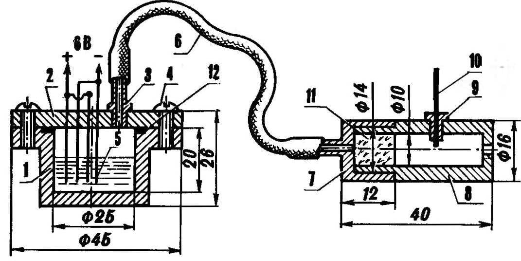
Formed in the electrolysis gas mixture is fed through a screwed in cover cropped nipple needle into the combustion chamber, whose body is carved out of aluminum or bronze. In the “breech” portion of the camera put a swab of glass wool (it prevents the breakthrough of flame mikroelektroniki). The power of four series-connected elements of the “Mars” (6B). Ignition — spark.
To simulate shot voltage 6V through microchamber is supplied to the electrodes of the cell. In less than a minute (for subsequent “rounds” 20-30 C) the device is de-energized, then it is possible to supply voltage to the electronic ignition. The spark jumps between the ignition electrode and the combustion chamber wall.
The device for imitation of shooting:
1 – body of Mikroelektronika (plexiglass), 2 — cover (plexiglass), 3 — nipple needle, 4 — screw MH (4 PCs), 5 — electrode (Nickel plate), 6 — nipple rubber, 7 — cover of the combustion chamber (aluminum, bronze), 8 – camera body (duralumin, bronze), 9— bushing-insulator (PTFE), a 10 — electrode spark plugs, 11 —swab (glass wool), 12 — rubber gasket.

Circuit of electronic ignition.
Transformer T1 is wound on the W-shaped ferrite core with a cross section of 7X7 mm, coil 1 contains 40+40 turns of wire PEV-2 of 0.61 mm, coil II — 2500 turns of wire 0.1 mm. PESO the Transformer T2 is wound on the annular magnetic core 10X6X3 mm ferrite 3000 NM. The winding of I contains 3 turns of wire PEV-2 0,31 mm, a winding of II — 600 turns of 0,1 mm. PESO as transformer bobbin used TOR the ignition of a moped. Capacitors C3 and C4 type of MBM 160V, VSІ — the dynistor Д227И, VS2 — КУ101Г thyristor, resistors R1 – R3 type MT-0,25, VDІ — diode МД218, VT1 and VT2 transistors П202, C1 and C2 — electrolytic capacitors of the type K50-6.
The described device perfectly mimics the sound and flash (in the dark) shot. Is in operation since 1982 and has established itself as an effective, simple, reliable and safe. Service is about adding 40-50 “shots” a few drops of water in microelectronical.
DAVYDOV, V. YAKOVLEV, Chelyabinsk
Recommend to read
 Aerosled “Swan-7”
Among the large family of "Lebed" (Swan) designs by Vitaly Konstantinovich Savitsky, the "Lebed-7" stands out for its bold layout of components and assemblies, successful centering, good... AT PEST — A FIRE EXTINGUISHER
There are many different tools, devices, equipment, value of which is primarily determined practical purpose, and their appearance and technical aesthetics are of secondary importance. I...
 Even perfectly executed a valid copy of a military ship or self-propelled artillery loses much if its design does not allow to simulate the use of the main weapon of the prototype. But most known simulators does not provide the sound similarities with a shot or hampered their placement.
