
 Training control line model airplane. The fate of each Antonov an-certovica has its first model. As a rule, later he gets the ironic name of “three stick — two string”, which in fact, it is quite true because of its very simple design.
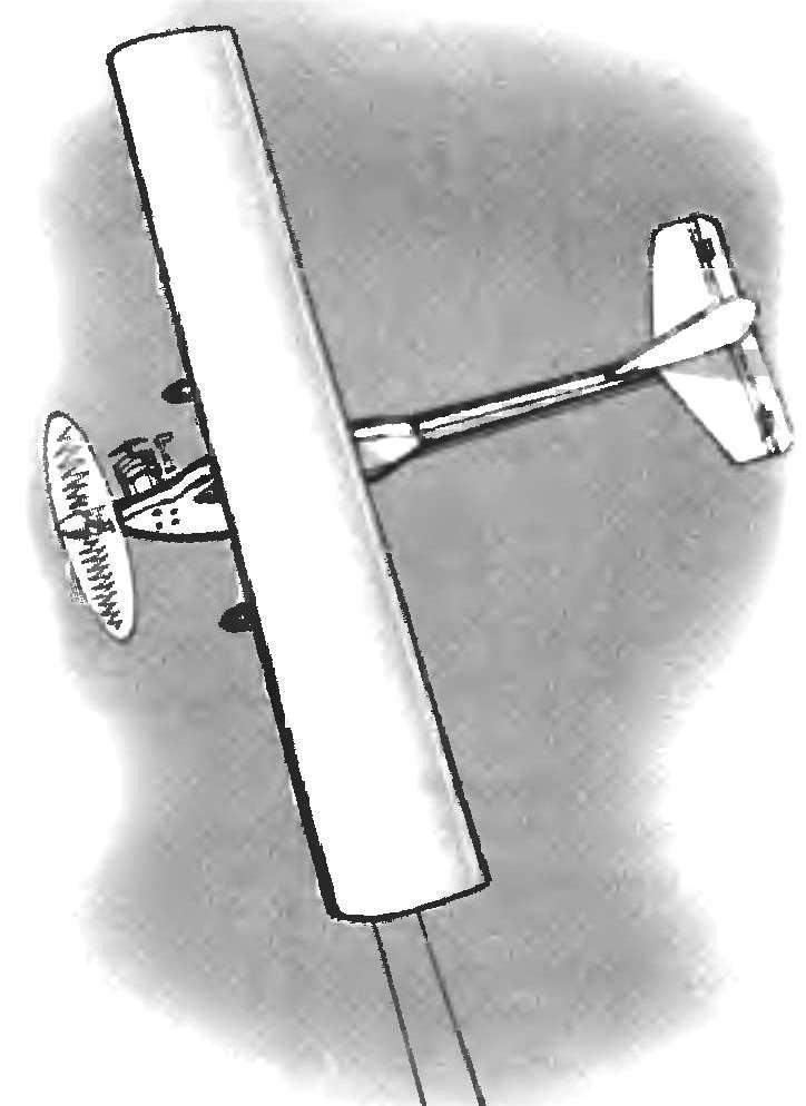
The first model definitely should be the second, because at first you can practice just take off Yes landing. Well, for those who have had to fly even a primitive model will want to master and elements of this class. It is for these modelers and designed training control line model airplane, dubbed because of its shape called “Guppies”.
I must say that the designs of the “Guppy” is not far from simple models for beginners. It is as simple to manufacture, however increased performance and less weight of this model allows the pilot / Modeler to learn the number of maneuvers.
“Guppy” is a control line model aircraft strut-braced-high-wing monoplane with a contoured fuselage, equipped with polutorametrovy engine MK-17 “Junior”.
The FUSELAGE of this model is going to epoxy glue a few parts. It is the Foundation of notched pine beams, cut from 10-mm plates integral with the engine frame. Beam of the fuselage has a variable cross — section-from 10×15 mm cockpit to 8×8 mm near the tail.
The upper part of the fuselage is made of lime, rack-jumper “the cabin” — of birch sticks. In the rear part of the fuselage (bottom) contour which is formed by a bent phony rack. Using stand-jumpers and the beam drilled holes with a diameter of 3 mm under wing mounting screws; for fixing these screws are designed nuts with thread M2,5, fixed in the beam with an epoxy adhesive.
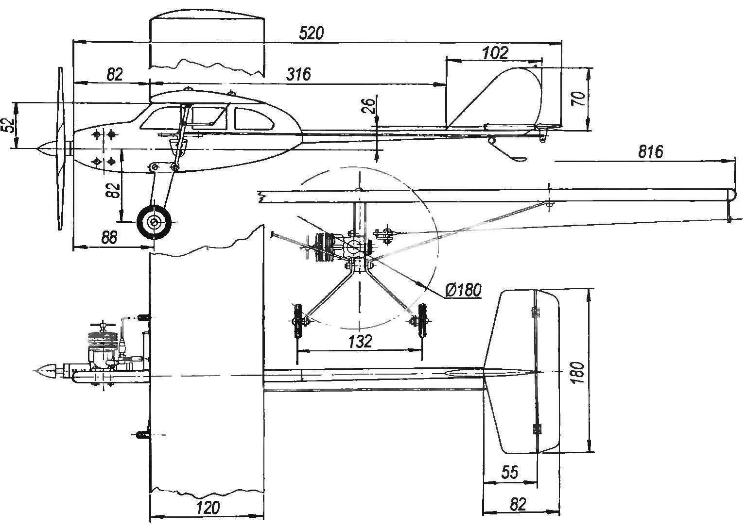
The geometric scheme of the training cord.
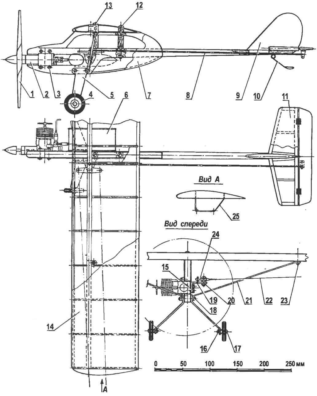
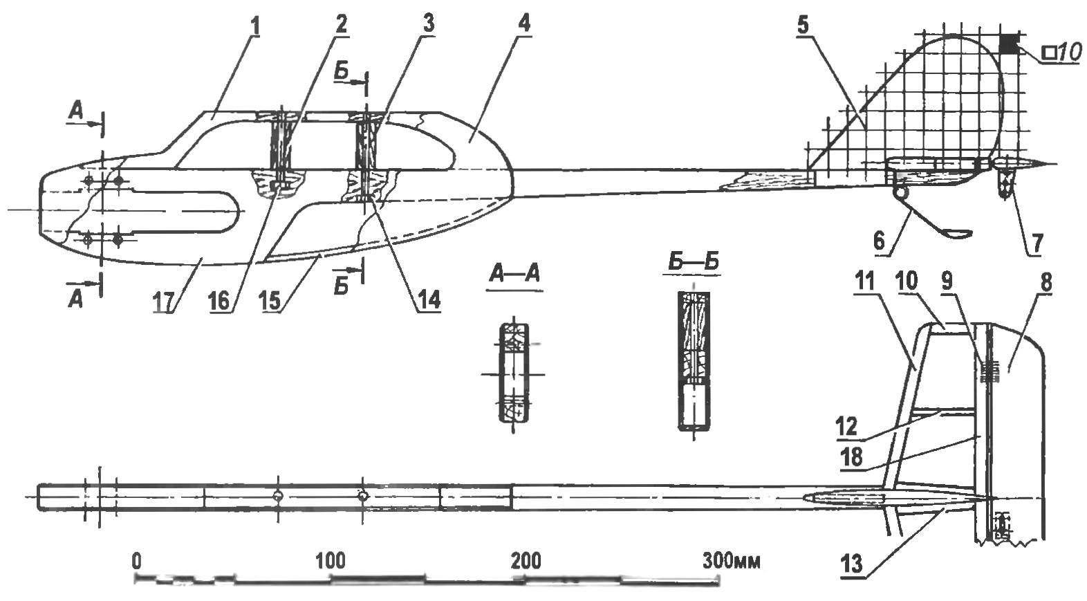
The design of the model:
1 — propeller; 2 — engine MK-17 “Junior”; 3 — a nut and bolt M3 (for mounting the engine to Motorama); 4 — wheel chassis; 5 — front chassis (aluminum, sheet s2,5); 6 — fuel tank; 7 — fuselage; 8 — control rod (aluminum knitting needle Ø2); 9 — keel; 10 — the crutch (the wire grade optical fiber Ø2); 11 — stabilizer; 12 — screw M2,5 (wing mount); 13 — screw M2,5 (strut mount); 14 — wing 15 — nut M2. 5 (for mounting bracket of the swing management and fuel tank); 16— nut M3 (for mounting to the wheel axis); 17 — axle wheel chassis (bolt M3); 18 — a bolt with M3 nut (fastening of strut and landing gear); 19 — bracket rocking control; 20 — M3 nut (for mounting the axis of rocking of the control); 21 — brace (aluminum, sheet s1); 22 — a leash; 23 — screw M2,5 (strut mount); 24 rocking control (duralumin, sheet s3); 25 — the guide cords — just right (OVS wire Ø0,5)
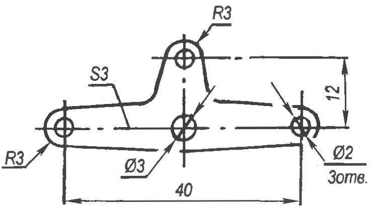
Rocking control (duralumin, sheet s3)
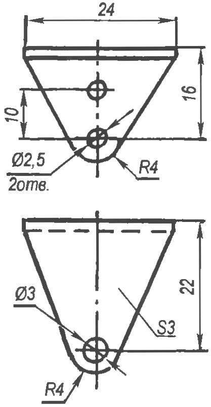
Bracket rocking control (duralumin, area with shelves s3)
Assembled the fuselage glued with two sides of 1-mm plywood, and right in the veneer is cut along the contour of the groove under the engine, and left such a cutout is not provided. After finishing and painting the fuselage in the area of Windows “cab” glued Mylar film.
TAIL fixed: and fin and stabilizer glued in the tail beam of the fuselage.
KEEL celebarty, it is cut out from plates with a thickness of 5 mm. Profile — symmetrical wing.
STABILIZER — stacked, Linden slats. Cladding made from thin Mylar film. The Elevator is balsa; with stabilizer it connects loops”eights” of the nylon thread. Hog steering height carved from duralumin with a thickness of 0.5 mm; on the steering wheel it is fixed with the brackets out of aluminum wire, rasklapanje on the part of the pig.
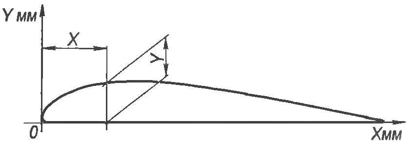
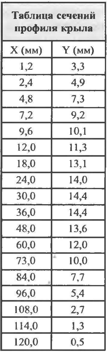
WING — single-ended PLANO-convex profile with good load-bearing properties. Its relative thickness is 12 percent. Wing design — patterned lining — made of metalized Mylar film.
The manufacture of the wing should begin with blank pieces of ribs from the fake plates of 3 mm thickness, spar pine shelves and a pine front and back edges. Below the ribs turned out the same, we recommend you to cut in accordance with the table of two duralumin airfoil template, placing them between balsa blanks, to pull their studs with nuts and jointly process them.
Fuselage:
1 — top part of the “cockpit” (Linden, . at s10); 2,3 — stand (birch, rake 10×10); 4 — covering the fuselage (plywood s1); 5 — keel (balsa plate s5); 6 — skid (wire, OBC 02); 7 — pylon rudder (aluminum, sheet 80,5); 8 — Elevator (balsa plate s4); 9 — hinge rudder (hinges-“eight” of the nylon thread); 10 — end rib of the stabilizer (lime, plate s4), 11 — the leading edge of the stabilizer (lime, plate s4); 12 – Central rib of the stabilizer (lime, plate s4); 13 — the Central rib of the stabilizer (lime, plate s4); 14,16 — nuts M2 mounting wing; 15 — sealing the back of the “cockpit” of the fuselage (basswood, rake 3×10); 17 — beam of the fuselage (pine, plate, s10); 18 – the trailing edge of the stabilizer (lime, plate s4)
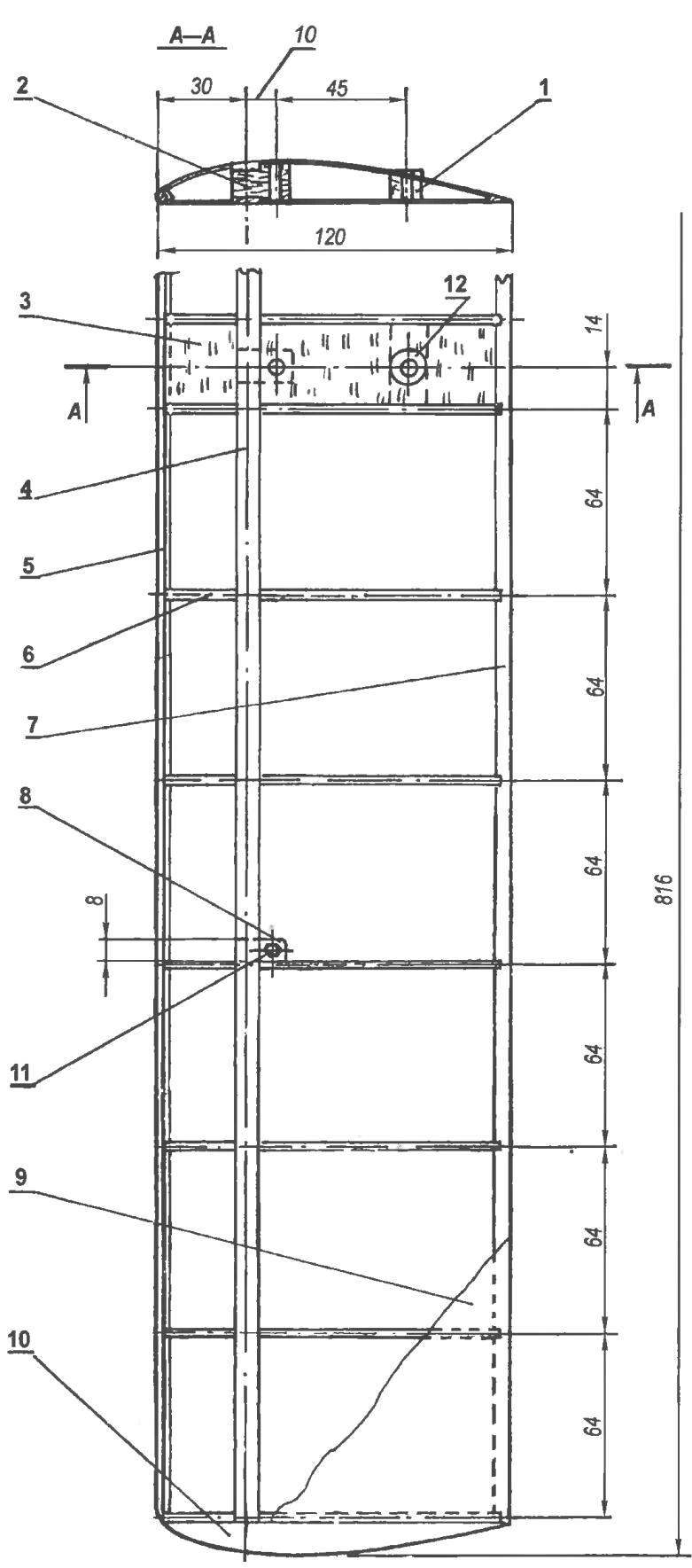
Wing:
1 — back panel (birch); 2 — front panel (birch); 3 — lining (Linden, an interline interval 1,5 s); 4 — shelf side member (pine, rack 8×3, 2); 5 — the leading edge (pine, battens 5×5); 6 — rib (Linden, s3 plate, 14 PCs); 7 — rear flange (pine, rail 10×3); 8 — Central insert (birch); 9 — wing (Mylar film); 10 — wing tip (foam); 11 — nut M2,5 (fixed in box with epoxy glue); 12 — support pad (birch)
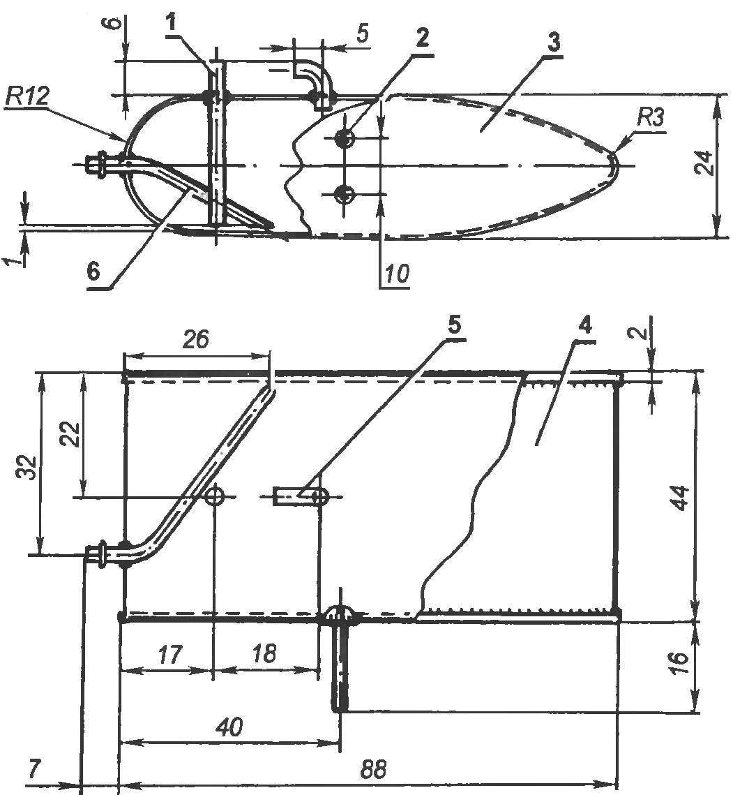
Fuel tank:
1 filling tube (copper tube 4×0,5); 2 — screw M2,5 (2 pieces soldered to the base POS-40); 3 — base (tinplate s0,3, 2); 4 — sides (tinplate s0,3); 5 — drain pipe (copper, tube 4×0,5); 6 — supply pipe of the engine (copper, tube 4×0,5)
The Assembly frame is most convenient to produce, on the slipway of the flat Board. Details first recorded it with the help of pins, rubber rings, stationery and clothespins, but after checking the accuracy of the Assembly (the frame should not have a twist, warps, etc.) seams spilled epoxy diluted with acetone to a density of sunflower oil. At the end of the rib right of the console, between the shelves of the spar, thread and glue is attached a lead weight with a mass of about 15 g.
The wing — of the Mylar film using glue BF-2. Stretch it is a small pad in the classic model of technology. Wingtips — foam.
Cord management guide is bent from a steel wire of the type OVS with a diameter of 0.5 mm. At the tip it is attached with epoxy glue.
ROCKING CONTROL is cut from a sheet of aluminum of a thickness of 3 mm; it is mounted on a bracket cut from dural area with flange thickness of 3 mm. the Latter is fixed on the left side of the fuselage.
CONTROL rod is bent from aluminum knitting needles 2 mm in diameter.
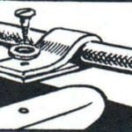
The FUEL TANK is streamlined soldered tinplate with a thickness of 0.3 mm. Shell consists of two bases and sides. The base will turn out the same if you make them from metal blanks using a simple stamp that can be cut from dural plates or even beech planks.
CHASSIS two-wheeled model, with tail wheel-a crutch. Plastic wheels with rubber tyres with a diameter of about 38 mm, from a child’s toy. Struts-spring — sheet duralumin with a thickness of 2.5 mm On the fuselage struts-springs are fastened by M3 bolts and nuts.
The STRUTS are cut from a sheet of aluminum 1 mm thick. the mounting of the strut to the wing with a screw and glued in the wing nut M2,5. On the fuselage brace that is fixed by the same bolt with nut, which is screwed to the chassis.
I. SILVER
Recommend to read
 SNOW TOBOGGAN ADRIATIC
Popular Yugoslav magazine "ABC-technology" in its two hundredth issue published material chief editor Vekoslava Bosnar about the amazing sled, designed by fans of the snowy slopes. ... THE SIMPLEST FLASHLIGHT
Yes, it's probably easier to not think. For the manufacture of such "Firefly" will need only a flat battery, the light bulb is 3.5 V and the two rubber rings or a bit of adhesive tape....
