LUNGING-SPEED “DUCK”

HORSE SPEED 
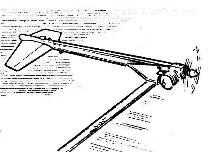
Unusual “Junior; model class г2А. the description and drawings which were published in “M-K” № 10, 1993, said a surprising impact on the foundations of our reasoning krukowski theorists. Disputes regarding this model were many, and in the end the boys to vychisleniya truth even built exaggerated flying “test layout”, which was legalized in their brain is given in the publication of the First display after “wow guys seems to have decided to take up the manufacture of good oblagorozhenny machine kapatiran engine. But then, it seems, even to his own surprise, he bowed to the idea to develop another idea, which ended the above-mentioned article, In the end we managed to implement an interesting high-speed model-a duck with it and also with the design and g are susceptible of experimental techniques we want to introduce followers aeromodelling class F2А. Perhaps it will help to create not only a “Junior” but also the current championship, very promising “duck”.

On the technical side, design new models, no problems brought. Greatly helped in the journal drawings of the high-speed normal aerodynamic scheme; to a large extent proved to be useful and experience gained in the circle, specializing in cord technique.

 
However, the main issue arose when determining the alignment of projected “duck”. At first I had to climb on various directories to find at least the principles of aerodynamics focus for the scheme; then, given the traditional high-speed models with stock alignment, you can begin the overall design and the detailed design of nodes. However, (fortunately, at this stage of the work, not later!) managed to find one “hitch”. She’s probably typical in General for all models with wing-band, and therefore it is special conversation.
 
The fact that the manufacture of the wing of a very large lengthening of the traditional model materials like pine, basswood and balsa to rely on more or less real torsional stiffness in the fuselage remote from the areas is not necessary. Perhaps the situation will change when applying a metal plating or construction of a wing from composite materials, particularly CFRP. However, having no experience of operating speed of this type to undertake a complex and time-consuming technology was pointless (considering the stage of working out of the scheme). When wooden planes wing rishlos to accept the idea that the bearing properties are only privateline areas.
In principle, nothing wrong with that. The model of the new type has a very small mass, and in General for high-speed cord machines required an area of 5 dm2 for flight is clearly excessive. The problem lies elsewhere. After all, if you consider that almost half of the wing operates in the directional mode, without exerting a noticeable effect on balance (!), it becomes clear — on the issue of alignment must be approached with extreme caution. Models conventional layout scheme with zadorspain stabilizer, perhaps, the influence of this factor is negligible. But, in fact, “turning off” from the process of creating a lifting force part of the wing area, we get the effective shift of the back focus of the camera. At constant centre of gravity position is formed only slightly overestimated the margin of alignment, which can be generally invisible and don’t affect the behavior of high-speed in-flight in all modes.
 
“Duck” aerodynamic focus will shift when non-rigid wing forward, which at best will reduce the stock alignment, and at worst (and more realistic) will lead to longitudinal instability, and complete lack of control of the model.
 
Knowing the characteristics of a non-rigid wing, it is easy to foresee the necessary measures in the design. In our case it is only an additional shift of the center of gravity forward, forming licheny stock alignment. In approximate calculations of the focus and the position of the center of gravity of the model wing area is recommended to take (at its scope within 2 m) equal to 0.4—0.5 of the actual. Span at 3 m correction factor will be equal to approximately 0.3. Finding the amendment with a high degree of accuracy makes no sense. Since the alignment is expressed as a fraction or percentage of mean aerodynamic chord of the wing (as it is in our case equal to 20 mm), even for such large changes in carrier square the absolute value of the shifting of alignment will be small. In any case, we recommend to carry out comparative calculations for the full wing and adjusted the weathercock effect.
 
Fig. I. control line speed model of the scheme
 
Fig. I. control line speed model of the scheme “duck” with the engine working volume of 2.5 cm3 and an elongated wing. In the basic version of the chassis front is given after takeoff to the fuselage by a spring and is fixed against lateral displacement due to the stacking of the rack in the fork.
 
 
Fig. 2. The power part of the model
 
Fig. 2. The power part of the model:
I — longitudinal beams (pine section SX 10 mm), 2 filler (foam stamps PHV), 3 — power insert (lime thickness 10 mm), 4 sheathing (plywood with a thickness of 0.8 mm or cardboard with a thickness of 0.5 mm), 5 — fuel tank; aka — cone, 6 — wing box (build from plywood and Linden), 7 inclined wall of the tank fairing in the area of the exhaust pipe of the engine 8 — engine, 9 — thin-walled aluminum fairing mounted on the glue on the crankcase, 10 — spinner, 11 — area of attachment of the engine on the model (ДІ6Т; 2 PCs), 12 — pad (birch), 13 — disc rocking (ДІ6Т), 14 — the screw MZ (soldering inside the tank), 15 — wall tank (soldering in the cavity of the fairing), 16 — wall of the box (plywood thickness of 1.2 mm), 17 — the front part of the wing (tight lip), 18 the outer edge wall of the box 19 — insert (Lipa, the rest of the wing — medium balsa), 20 the mounting bracket of the engine head (ДІ6Т), 21 — the guide rope (thin steel spring glued to the side of the wing). Profiling of the wing corresponds to the previously published model.


R and p. 3. The nose part of the model with feathers
 
R and S. 3. The nose part of the model with feathers:
I — edge (lip thickness of 3 mm), 2 — stabilizer (lime, 3 mm thick), 3 — hinge-hinge hinge steering, 4 — wheel height (balsa 3 mm thick; they stick to the lime Nastya tail, and only after profiling the wheel is separated using a jigsaw), 5 — steering bracket (wire OVS 0 1.8 mm, drawn through the stabilizer sealed in thin-walled brass tube), 6 — fairing that protects the horn bracket when turning models, 7 — beam spars (pine section ЗХ10 mm) 8 pull steering (OVS wire diameter 1.2—1.5 mm, drawn through the body of the model in the long Solomin), 9 — straw bent over the flame end, 10 filler (foam stamps PHV), 11 — nasal boss (Linden thickness of 10 mm; the groove under the stabilizer is cut after Assembly of the fuselage).


R and p. 4. Fuel tank-fairing
 
R and S. 4. The fuel tank fairing.
For “duck” and is another characteristic feature associated with non-rigid wing. If the model of a conventional circuit performs the wing (see the publication “M-K” № 10, 1993) the proposed execution of the function of one of the cords and therefore constantly strained in flight (and, in addition, successfully “hung” on the line of the center of pressure at 25% chord of the profile), then the “duck” is more complicated. At first it seems that the film is indeed suspended on the brackets in the directional mode for two kordovye threads, generally no problem will bring. But this is not so. At high speed flight, if you do not take constructive measures, very high probability of occurrence in a specific tape flutter, known in aviation as the torsional oscillations of non-rigid, long and narrow ailerons. Well known not only this feature, but also measures to prevent such oscillation. Master — the use of weight balancing. To really put this into our model is a snap, given the existing brackets and cord guides for small linear mass of the wing structure. To check the degree of balancing of the isolated wing model is hung on cords stretched two segments, and then selected the weight of the weights on the forward shoulders of the brackets.
 
From a technological point of view, the new speed model is not any more difficult, and its construction is clear from the cited figures. The only thing you need to consider when the transition to the scheme “duck” compared to conventional aircraft — the engine begins to operate at off-design position relative to the propeller thrust. Therefore, you need to see how to get the bearing clearance of the crankshaft. In addition, it is useful to know that in order to realise the benefits of the scheme “duck” are special propellers of smaller diameter and increased pitch.
 
V. SHUMEEV, head of airmodelling mug

Recommend to read

  • FUN FOR ADULTSFUN FOR ADULTS
    Shown in the figure and pattern of a simple toy has survived from the ancient Celts. Most interesting is that it was a pleasure to play not only children but adults as unusual properties...
  • AND LASER AND PLOWAND LASER AND PLOW
    — Go to Nizhneudinsk — said to me in the Irkutsk regional Committee of the Komsomol. — Where the station Director is an enthusiast of invention, teaches kids to experiment. We hold...