
 In the laboratory, missile and space modeling of the Moscow city Palace of children’s (youthful) creativity of the work on the creation of models-copies of the booster (PH) “Soyuz” was launched in 1984 with the arrival of the Chelyabinsk rakatomalala Alexander Left, while a student at the Moscow aviation Institute. In developing the model tried to take into account not only all the achievements in the construction of models-copies PH “Union”, created in different years domestic rakotomalala — S. Parnevik, V. Rozhkov, A. Klochkov, A. Korchagin, V. hohlovym and A. Bachey, but not to repeat the shortcomings of their designs.
To create the model took 1:50 scale to prototype as the most simple, allowing to fit in the layout of the nozzles of the Central unit are four serial model rocket engine MRD 5-3 with a diameter of 13 mm or 11 and get off mass, not beyond the limit set by the rules. The main material of the buildings chose the fiberglass, and frames for supporting the docking and undocking of certain parts of the model are aluminum and magnesium alloys.
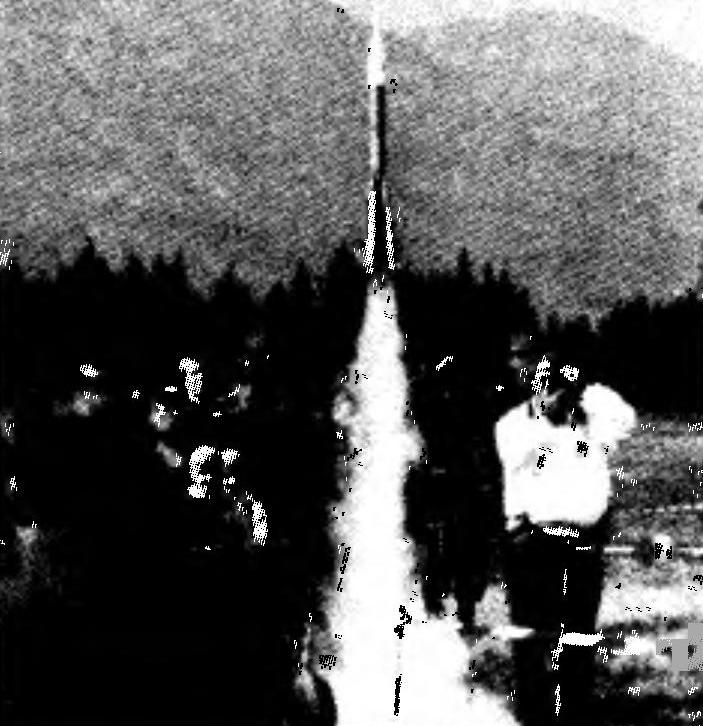
After nine years of hard work on fine-tuning of the model A. Left in 1993 he won the European championship. Model-a copy of the first attempt has done a beautiful flight in a three-stage configuration, it is highly appreciated by the judges.
This was accompanied by work on a new version. The basis for it was a set of high-quality photos PH “Soyuz-2” with the spacecraft (SC) “Soyuz TM-12”. They were made by a photojournalist for TASS, the Soviet Pushkareva by order of the newly created Federation of flying sports of Russia with the assistance of the National flying club. Photography made it possible to develop drawings and make almost a perfect set of technical documentation on a specific prototype, as required by the rules the FAI Sporting code for space models and to start building a new model of a copy that was ready for the world Cup in 1994, the Revision was allowed, if necessary, to perform four-stage flight, with the division into twelve parts, according to the following cyclogram: start — 0 C; the side blocks — 1,5—1,8; reset the layout of the propulsion system of emergency rescue system (PS SAS) and fairing (TH) — 2,3—2,5; the launch of a model rocket engine (MRD) 3rd stage and the separation of the Central unit is 2.8—3, the ejection recovery system Central unit — 4,8—5; launch of MRD layout KK — 4,5—4,6 s; ejection of the recovery system 3-tier — 6,6—7; the separation of layout KK — 8,5—9.
The European championship of 1997, which took place at the First World air games and world Cup 1998 was again victorious. The successful flights made by the model A. allowed Left turn from three-time European champion and first to win the title of world champion. Seven-year statistics of the flight-models at the international competitions has confirmed the correctness of underlying design decisions, which allowed even in case of accident to avoid serious damages and to vary the composition and number of flight demonstrations depending on the results of the bench evaluation and the prevailing conditions of wrestling. The scheme of fastening and separation of the side units can be used on all models-copies of a prototype batch of the scheme.
Model-a copy of PH “Union” with the spacecraft “Soyuz TM-12” consists of a Central unit (CB) 2, four identical side blocks (BB) 1, adapter 3, 3 stage 4, 5 KK layout, the two halves of the fairing 6 and do mock CAC — 7. The entire model consists of twelve parts, each of which has its own system of salvation. Power source (battery) on-Board power supply located in the front compartment of KK layout. Side grid is carried out on gargrota and connects through the electrical compartments of the KK layout, 3rd stage, adapter and the Central Bank. To reset, start the engines of the 3rd stage layout and KK used electrosupply installed in the adapter and layout of KK, respectively. To stabilize the flight of the 3rd stage is provided by the unit drop-down stabilizer, and the flight 2nd stage regulator, console, which is installed on the housing of the Central Bank. During the powered flight phase of the 1st stage they are in the slots recessed into the hull BB.
The distribution of MRD by steps as follows: in four of the Central Bank of MRD (one 3 and three Wed 10-3); each BB one by one mrad A-3 or b-3, reduced to 3 N-s total impulse; one of MRD In-3-3 3-tier and one mrad A-3-3 in the layout of KK. The simultaneous launch of eight MRD side blocks and Central blocks is provided with Perekrestok. The engines of the Central Bank give commands to the flight demonstrations, In-3-0 gives fire a beam for triggering the pyrotechnic device, the shooting of the BB. The first and second Wed 10-3-0, by closing electrical contacts movable sleeves when triggered, batches of gunpowder, form the team to reset and start the engine of the 3rd stage. Third Wed 10-3-2, its linkage expelling charge ejects the recovery system of the Central Bank. To generate a desired sequence of the MRD flight In a 3-0 first Wed 1 0-3-0 modified to reduce the length of their work (by reducing the length of the solid propellant charge). The engines of the 3rd stage layout and QC to improve the reliability of their ignition deployme equipped with nozzles.
The Central block (CB) 2 consists of a body and a removable tail section. Three frame (upper 2.22, the average power of the lower 2.5 and 2.14) connect and centered between an upper cone 2.3, a housing with conical and cylindrical parts 2.6 and 2.2 of the inner tube, which serves as a parachute compartment. It is a labyrinth reusable wad 2.9 and 3.6 parachutes adapter and Central unit 2.7. To protect the cylindrical part of the thermal impact during the ejection recovery system, the gap between the inner tube and the cylinder filled with balsa 2.30. At the bottom of the cylinder are mounted four focus 2.33, which fix the engine compartment, and has four holes for the passage of the piston BB. In the holes of the upper frame fixed 2.22 snap ring that is bound through the attenuator chute 2.7.
The average power of the frames of the Central Bank are four spring-loaded pusher 2.23, terminals which extend outward through holes in it. On the cylindrical shell of the Central Bank, in mutually perpendicular planes at BB, four console mounted stabilizer 2.10, which is placed directly behind the console retainer bracket 2.12, tilted forward the supporting planes. The retaining bracket is formed by two cross-shaped articulated plates, passing through holes in the housing of the Central Bank.
Tail section (HO) is composed of three frames, top (pyrotechnic) 2.30, 2.33 and lower average 2.14, which unite and centered housing 2.15 and 2.16 four tube engines, located at the axes of the dummy nozzles. 2.33 average frame consists of a metal ring and the balsa wall 2.34. MRD installed in the tubes HO and the fixed pins 2.31. In the upper parts of the two tubes is located an electric contact with terminals of electrical connectors which are connected to the onboard grid. Docking and centering HO with the body of the Central Bank secured the landing shoulder of the upper 2.30 and 2.33 of the middle frames. At the top (pyrotechnic) the frame is made of four slots and four cylinders, arranged perpendicular to the axis of the frame. The grooves serve for the passage of thrust 2.32 Central Bank, which fix the position of the engine compartment when it is rotated relative to the housing. In this combined openings in the housing of the Central Bank with the cylinders of pyrotechnic frame. Also in the fireworks frame is made of a Central cavity with a sealed screw plug 2.28 and connected by openings in the cylinders and the blank pipe of the first engine. Upon completion of MRD In-3-0 serves fire a beam into the Central cavity. He ignites an additional charge of gunpowder, which sends the beam into the cylinders. From beam to ignite the pyrotechnic sample in 1.11 BB pistons inserted in the cylinders. The hot gas pushes the pistons of the cylinders, firing the BB. Reliability is achieved by selection of the diameter of the holes in the bulkhead pyrotechnic precluding rapid gas flow from one cylinder to another.
Design BB 1 is formed by housing 1.2 and the tail section. In the front of the case mounted to the cap 1.1, with a focus of 1.8, and the location of the pistons strengthened from the inside to medium frames 1.9. In the lower part of the housing is a connecting frame is 1.25, the design of which ensures quick Assembly of the tail section. The latter is formed by the housing 1.7, and two frames, upper and lower 1.23 1.26, and consists of two parts — a metal ring and the balsa wall 1.12. Both frames also serve for mounting two tubes 1.15, 1.17 (parallel to the axis of the block), also santaromana with a pair of dummy nozzles 1.24 unit located closer to the center. One of them is 1.17 mrad compartment, the other 1.15 a guide for a retractable parachute compartment 1.18 (VPO). He plugged the top with a tube 1.16, in which a pin 1.14, sliding along the guide grooves 1.3, cut parallel along the axis of both tubes. 1.13 spring fixed at one end over pin 1.14, and the other for the end of the tubing actuates the VPO, forcing him to move beyond the end of the block. At the bottom of the compartment glued the thread loop, which through the rubber shock absorber is attached to the parachute 1.20. Articulation and centering of the BB housing and the tail section is secured the landing shoulder of the upper frame 1.26 the tail section and its rotation relative to the housing. When this occurs, the engagement of the projections on the front bulkhead of the tail section with the slanting grooves of the rear bulkhead of the enclosure.
Side blocks pristykovyvayas to Central as follows: parachute compartment 1.18 utaplivayut to the stop — pin 1.14 it is the position in which it can engage with the console retainer bracket 2.12 of the Central Bank; focus 1.8 tip rests on the pin pusher 2.23 of the Central Bank and move it forward; the Central block is rotated around the stop; console 2.10 stabilizer and bracket 2.12 go through the slot into the body BB; pin 1.14 parachute compartment engages with the support plane of the retaining bracket 2.12; 1.11 BB piston enters the corresponding cylinder pyrotechnic frame 2.30 HO Central unit, and the parachute compartment is fixed in the closed position.
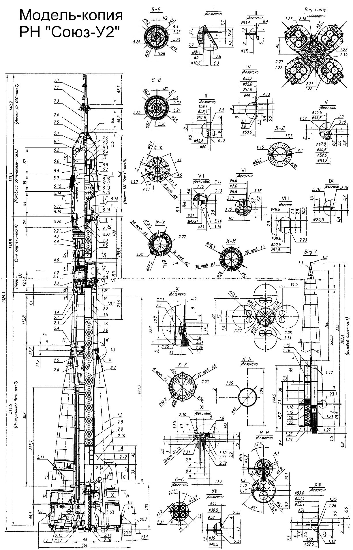
Model-a copy of “Soyuz-2”:
1. Side blocks:
1.1 —headroom; 1.2 — body; 1.3 — guide slot; 1.4 — based vehicles; 1.5 — axle steering; 1.6 — helm console; 1.7 — body tail section; 1.8 — emphasis headroom; 1.9 — the average frames; 1.10 — threaded sleeve; 1.11 — piston; 1.12 — wall of the upper bulkhead of the tail section; 1.13 — spring, parachute compartment; 1.14 — thrust pin; 1.15 — guide tube of the parachute compartment; 1.16 — sliding tube; 1.17 — tube engine compartment; 1.18 — parachute compartment; 1.19 stub parachute compartment; 1.20 — parachute;
1.21 stub engine compartment; 1.22 — centering bushing parachute compartment; 1.23 — bottom frame tail section;
1.24 — dummy nozzle; 1.25 — connecting frame; 1.26 — upper frame tail section; 1.27 — MRD 3/4B-3-0
2. Central unit:
2.1 —gargrot; 2.2 — inner tube; 2.3 — top cone: 2.4 upper guide ring; 2.5 — medium power frame; 2.6 — housing with conical and cylindrical parts; 2.7 — parachute: 2.8 — tape wad; 2.9 — labyrinth wad; 2.10 — console of the stabilizer;
2.11 — lower guide ring; 2.12 — retaining bracket; 2.13 — pin plug; 2.14 — lower frame tail section; 2.15 — body tail section; 2.16 — pipe of the engine; 2.17 — fairing; 2.18 — MRD In-3-0; 2.19 — Wed 7,5-3-0; 2.20 — СРД10-3-0;
2.21 —Wed 10-3-2; 2.22 — upper frame; 2.23 — pusher;
2.24 — spring pusher; 2.25 — sleeve; 2.26 — resistant ring; 2.27 — cap: 2.28 — tube: 2.29 — balsa; 2.30 — top pyrotechnic frame; 2.31 — pins MRD; 2.32 — stops; 2.33 — average frame tail section; 2.34 — wall bulkhead
3. Adapter:
3.1 — Electrosoul; 3.2 body; 3.3 — farm; 3.4 — housing of the instrument compartment of the Central unit; 3.5 — thrust cylinder; 3.6 — parachute; 3.7 — upper frame; 3.8 — insulation; 3.9 — lower frame; 3.10 — upper support ring farm; 3.11 — heat tube; 3.12 — conical cover; 3.13 — lower support ring farm; 3.14 — threaded frame; 3.15 — threaded sleeve; 3.16 — tube; 3.17 — starting glass; 3.18 — bottom; 3.19 — centering frame; 3.20 — pad electrical connection side
4. The third stage:
4.1 — insulation plate; 4.2 — the outer body; 4.3 — inner case; 4.4 — parachute; 4.5 — labyrinth wad; 4.6 — spring clip MRD; 4.7 — MRD 5-3-0; 4.8 console stabilizer; 4.9 — average frame; 4.10 — sleeve rolling block stabilizer;
4.11 —axis of the console; 4.12 — upper frame; 4.13 — connecting frame; 4.14 — the end frame; 4.15 — pad connector
5. The layout of the KK:
5.1 — the tube shooting of TH; 5.2 — housing top BO; 5.3 — frame; 5.4 — battery D-0,125; 5.5 — wad; 5.6 — housing lower part BO; 5.7 — tube base shooting TH; 5.8 — Electrosoul; 5.9 — inner housing SA; 5.10 — cap; 5.11 —parachute SA;
5.12 — housing SA; 5.13 — parachute APO: 5.14 — side electrical connector; 5.15 — inner case APO; 5.16 — console stabilizer; 5.17 — body APO; 5.18 — centering bushing; 5.19 — pins electronica with the 3rd stage; 5.20 — MRD And-3-4; 5.21 — Electrosoul; 5.22 — sleeve elektrozapalom; 5.23 — medium frame; 5.24 — lower frame; 5.25 — the inner cylinder; 5.26 — locking screw; 5.27 — torsion spring; 5.28 to unclamp the contact; 5.29 — pad electrical connection side
6. Fairing:
6.1,6.2 — halves GO; 6.3 — upper conical frame; 6.4 — average frame; 6.5 — lower frame
7. The layout of DU CAC:
7.1 —upper case; 7.2 — layout of the nozzle block; 7.3 — lower case; 7.4 — base; 7.5 — foot cone; 7.6 — a, 7.7 — MeV cylinder; 7.8 — pusher
Pins 1.14 parachute compartments, based on the forward reference plane consoles locking bracket 2.12, make the side blocks to pull over to Central. Spring pusher of the Central Bank and 2.24 1.13 parachute compartment BB, acting in different directions, is securely fixed to a BB. Dummy couplers, as in the prototype, are attached to the brackets via universal joints. When shooting BB he turns around the pin pusher 2.23, which after the release of the engagement of the pin 1.14 with a retaining bracket 2.12, pushes the block down. At this point the parachute compartment 1.18 extends and enacts parachute 1.20.
On top of the frame 2.22, the Central Bank relies adapter 3 formed by the tail section of the unit And 3.2, farm 3.3 housing 3.4 the instrument compartment of the Central Bank. Inside it is mounted a threaded bulkhead 3.14, in which resistant screw cylinder, 3.5, 3.19 centering frame which, together with the landing band instrument module provides docking and centering of the transition compartment 3, with the Central Bank (2). At the bottom of the thrust tube of the cylinder is glued into the bottom of 3.18 with a spring ring which is attached via the shock absorber 3.6 chute adapter. Tail section of the 3rd stage is formed by the housing 3.2 and two frames, top bottom 3.7 and 3.9. The latter consists of two parts: the actual frame and the upper support ring 3.10 farm. Inside the compartment, between the frames, closed by the heat insulation 3.8 out of balsa.
Farm 3.3 formed soldered lengths of thin-walled tubes of copper-nikelevogo alloy. Into the tubes of the upper and lower ends of the farm-inserted wire rods fixed in the soldering holes of the upper and lower support rings. The lower ring 3.13 worn on the belt housings 3.4 instrument compartment. In the Central hole mounted thermal insulation tube of 3.11 with a conical lid 3.12, into the threaded hole in which is screwed the glass launcher 3.17 engine 3rd stage. It consists of glasses with a slot into which is inserted Electrosoul 3.1, and put on top of the movable tube 3.16 closing a slot when you shift down. These details are recorded and santarromana the instrument compartment end of the thrust cylinder of 3.5 for its installation. The grid transfer compartment through the connectors associated with the circuits of the Central Bank and 3rd steps. Electrosoul connected to the sockets of the electrical connector mounted on the top head of the instrument compartment.
On the 3rd stage 4 uses a modified 4.7 mrad with launchers supply nozzle. Its use, on the one hand, ensures reliable starting of MRD, at the expense of his time in the starting glass of 3.17 adapter, and with another — simple installation and motor mount. Design 3-tier is formed by an outer 4.2 and inner 4.3 buildings that are connected and centered through the top and middle of 4.12 4.9 frames. At the bottom of both enclosures are mounted, respectively, a connecting end 4 and 4.13.14 frames that provide docking and centering adapter 3 (the tail section of the unit And 3.2) and hitting a nozzle 4.7 mrad in the starting glass of 3.17. The top of the inner case serves to dock the layout KK 5. The middle part is a parachute compartment, which houses a labyrinth wad of 4.5 and 4.4 parachutes 3rd stage and the layout of CC (when you start the 3-step version), and down is UP. End frame 4.14 internal housing has a disc shape in the center made a hole for the passage of a nozzle MRD having outer diameter of 6.5 mm., Engine 4.7 mounted in the top tier and fixed, as a focus, spring bracket 4.6, the ends of which lead into the holes TO the inner hull.
Due to the small length of the caudal compartment of the unit And 3.2 that prevented to the console of the stabilizer sufficient space to stabilize the flight of the 3rd stage, they had to combine in the movable block. Its sleeve 4.10 slides on the outer surface TO under the action of the rubber isolator and bracket wire fixed axles 4.11 4.8 eight consoles connected to the top of the rubber ring, which Nativas, creates a moment for their disclosure. When docking the 3rd stage to the adapter console of the stabilizer stack and the block is moved forward, partially utaplivaja it inside step. When you separate the steps, he moves down at the same time revealing the console.
On the outer surface of the outer body closed by garrote, pass the wire side circuits ending in the area of the docking frame 4.13 pins from the connector. On the other hand, the circuit ends with a connector 4.15 fixed to the upper frame and 4.12 connecting the 3rd tier with side grid layout KK. There are installed and insulation plate 4.1, normally closed contacts of 5.28 on the layout of KK. Through the holes in the frame threaded snap ring, which through the attenuator attached to the umbilical cord of a parachute 4.4 3rd step.
The layout of the KK 5, as in the prototype, consists of three compartments — front, middle and tail, the shape is close enough repeating the external contour of the corresponding compartment of household, the lander and the instrumentation and propulsion compartment of the spacecraft “Soyuz”. In the front compartment (BO), formed by the upper and lower 5.2 5.6 parts placed on-Board power supply 5.4, and the tube is shooting 5.1. Average 5.23 and 5.24 of the lower frames of the lower shell is fastened and centered inner cylinder 5.25 with a tube ejection 5.1. In addition, in the middle frame, in a circle, made four groove in which is placed a disk of Nickel-cadmium batteries D-0,125 5.4. The inner cylinder and the lower end of the body of this part to form the landing belt for docking with the middle compartment. On the front side of the case mounted butt the frame, two threaded holes, and at the lower end of the upper part of the sealed counterpart butt frames with screw holes. The front end of the body top ends by a tube, which is tube ejection. Both parts are articulated and santarromana planting bands of the frame, and the junction of socotran screws 5.26. On the outer surface of the lower part of the front compartment is derived on-Board connector for connecting power and charging the batteries.
On the upper end of the middle compartment 5.12 (SA) is a cylinder, which together with the housing forms a landing shoulder dock with the front compartment. In the cylinder fixed to the ribs of the tube base shooting the 5.7, GO with a slot under Elektrostal 5.8. Through the holes in the upper part of the body, out output connectors to connect power and elektrozapalom 5.8 reset, and its bottom end is located inside the frame for coupling with the tail section. In the lower part in the area of the junction with the tail compartment is fixed a pin junction 5.14 electrical connection to the mains the tail section, evenly installed around the circumference of the housing.
The rear compartment layout (APO) CC is formed by the housing 5.17, in which the upper and lower frames fixed and scandinavan inner case 5.15. Its lower part is UP, in which is mounted mrad 5.20, and at the lower end is fixed a centering bushing 5.18, supporting the docking and centering of the 3rd degree. The bushing, through the shock attached to the parachute mock-KK (for three-stage variant of the flight), and its end is screwed a bushing with elektrozapalom 5.22 5.21. On the outer surface of the housing, near the junction with the middle compartment uniformly around the circumference of the housing socket junction with the grid middle compartment, and the lower frame 5.24 5.29 connector for communication with the 3rd tier and the liaison group 5.28 from the solenoid. Her circuit occurs at the moment of separation from the KK layout, 3rd stage, and generates a command to start the engine. On the inside of the tube is also fixed the control Board connector for which the housing compartment is made in the window.
Articulation and alignment of the compartments of the KK layout provided between the landing shoulder and the locking joint of front and middle pin passing through transverse openings in the belts. Inside the junction of the middle and tail compartments is placed a split compartment with their parachutes 5.11 and 5.13.
To ensure the flight stability of the QC layout in the gap between the inner housing of the tail compartment and the outer casing and placed sixteen consoles 5.16 drop-down stabilizer. Console bonded in pairs on the support ring located on the outside in the lower part of the body the tail section, and expanded under the action of the torsion springs 5.27, wearing the same ring. When folding forward flight they are recessed into the housing grooves, and the grooves come into engagement with the inner housing 4.3 3rd stage and fixed in the closed position.
Fairing (TH) 6 consists of two parts 6.1 and 6.2. On their inner surface are cut 6.3 upper, middle and lower 6.4 6.5 frames. The upper frame 6.3 has a conical shape and serves to dock with the layout of DU SAS (7). Middle provides rigidity to the torsion through the holes in the threaded snap ring, which through the rubber shock absorbers are attached to parachutes. The bottom frame is 6.5 for coupling with the upper frame 3-tier 4.12. Alignment with the longitudinal axis of the model-copies provided of the landing shoulder of the lower frame 6.5 with the 3rd step and the conical belt of the upper frame 6.3 with cone 7.5 DU CAC. Inside the junction of the halves of the fairing, both sides and along the entire length, strengthened by the protrusion on one half entering the return groove on the other, and a closed outside that simulated full-scale joint.
The layout of DU CAC 7 formed by the upper and lower 7.3 7.1 buildings, layout 7.2 nozzle block, base 7.4, 7.5 of the reference cone and the landing cylinder 7.7. The corps articulated a threaded rod passing through the housing nozzle block. By the end of the bottom housing 7.3 using thread attached to the supporting cone 7.5, pressed bore cylinder 7.7. Cone ensures the centering and fastening of the halves. Landing cylinder serves to centering of the layout do the SAS with the longitudinal axis of the model-copy. The upper part of the fixed antennae of the follower 7.8 that when shooting, resting at the top of the frame, move it up and tossing the halves aside. At the bottom of the planting cylinder is a snap ring attached to tape 7.6 DU CAC.
Vladimir MINAKOV, honored coach of Russia,
head of the Department of technical creativity MGD(Yu)T
Recommend to read
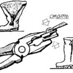 AND LOCK LIKE NEW
It happens that the fastener-"lightning" on jackets, boots, trousers or skirts after some time becomes hard to hold. If all its teeth in order, the case is in lock-slider — weakened his...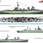 “MERCENARIES” — NAKED AND IN ARMOR
We have already talked about the fact that the Mediterranean powers, France and Italy after the First world war were almost no modern cruisers scouts that were at the end of battles is...
