 (The end. Start at # 5 and 11 ’02)
The carrier rocket “Soyuz-2” spacecraft “Soyuz TM-12”. The article “Soyuz” space survivor” (“modelist-Konstruktor” No. 5’02) it was told about creation and tests of the spacecraft and the carrier rocket, which became the prototype for a whole series of these ships and missiles. Their modifications were successfully used for manned flight programs of national long-term orbital stations “Salyut” and “Mir”, and now — to fly to the International space station (ISS). In the same issue of the journal was given detailed drawings of the carrier rocket “Soyuz-2”.
In the publication “model-a copy of the champion” (“modelist-Konstruktor” No. 11’02) discussed the design model of the rocket, built in Moscow city Palace of children (youth) creativity former Chelyabinsk rakatomalala, now world champion and multiple European champion A. Left, and printed her drawings.
Now the final material is about the technology of making a model. Admittedly, the model is complicated. Judge for yourself: the realism of its flight provides ten engines. 4-speed version, it rusticoville into 12 parts, all of which are equipped with recovery systems. For this delicately thought out mechanization model. Even if the building it for you, familiarization with the manufacturing technology will enrich the Arsenal of your knowledge and skills.
Tooling and starting device. For the construction of models-copies of the booster (PH) “the Union-2” with the spacecraft “Soyuz TM-12” is necessary to produce a large amount of tooling:
— set of metal bars (17 PCs.) for coiling casings, tubes and compartments. Their outer surface the same shape and inner dimensions of the case and compartments taking into account the thickness of their walls. Mandrels are machined on a lathe from a tough aluminum alloy D16T for instance, or any steel, polishing cloth and polished;
— set of dies and punches for cutting hatches and formaci different fairings and riveted panels, including thermal protection to the caudal compartments of the Central and side blocks. They milled steel or hard aluminum alloys, the working surface of the grind and the cutting edges is adjusted to the desired condition work. In addition, on the working surfaces of dies for die-riveted body panels on a milling machine using a special fixture is applied to the image-riveted and welded joints;
— die and punches for forming boxes of Harrachov (milled from a thick acrylic plastic);
— matrix for casting of epoxy resin simulate the bolts of the joints of the block. They are made of duralumin plates;
— metal mold for the injection molding of polystyrene dummy nozzles (machined on a lathe);
— soft forms (head of the Central unit — the Central Bank, the reasons and the actual aerodynamic condition, front cover bottom CB; grounds of nozzles of the propulsion system of emergency rescue system — do CAC; elements of reinforcement lattice stabilizers fairing — TH) cast of a silicone sealant for the manufacture master models of these parts of the design model;
— matrix for the manufacture of the fairing maneuvering thrusters CB cast from epoxy resin on the corresponding master model which is then used as a punch;
two fixtures are machined out of aluminum to build the farm and the transitional compartment, which allow to obtain the required relative positions of the mounted parts and components and to ensure alignment;
— templates for cutting out the combs amplification and docking simulation of chemical milling instrument compartment of the block And cut from thin glass fiber;
— knurling for printing spot welding. The basis for them are the gear teeth with the corresponding step.
 To ensure simultaneous launch of model rocket engines (MRD) blocks 1st and 2nd stages was developed and manufactured Perekrest whose peripheral tubes located on the sliding consoles. This is due to the fact. what is the location of the side relative to the Central blakoe not fixed rigidly and there may be some deviation of the distances between their engines. Console are cylinders with holes for the transmission of fire and screw cap. Their attachment to the Central part provides the mobility using split brass sleeve, which is locked with a screw.
 The manufacture of parts. All billet housings model is made by winding fiberglass soaked in epoxy resin ED-20 by standard techniques of rocket modeling. The outer buildings consist of two layers of fiberglass weighing 60-70 g/m2, two layers of fiberglass 40-45 g/m2 and one layer of fiberglass with a density of 25 g/m2.
The inner and guide tubes, BB and parachute compartments amateaur of three layers of fiberglass with a density of 60— 70 g/m2, tube motor compartments of Dauch layers of such fiberglass, and the pipe resistant cylinder adapter—five layers.
On the surface of the casings and rocket stages, apply two or three layers of primer (lacquer AK-20 and epoxy primer). After drying, the outer poverhnosti vnoel sanded with fine sandpaper to solicit Rooney and smooth surface. Then they marked, cut and removed from the mandrel.
On the outer surface of the workpiece inner tube CB glued with epoxy glue sheet balsa and light ply with a thickness of 1-1,5 mm the Workpiece is clamped on the mandrel and the Chuck of the lathe and face piercing holes, the outer diameter of the pipe, which should be slightly smaller (0.05—0.1 mm) inner diameter of the cylinder’s body. Next, the workpiece is cut and removed from the mandrel.
In motrico (two layers of fiberglass with a density of 60-70 g/m2 and one layer of 25 g/m2) impregnated with liquid epoxy resin and pressed by the punch into the billet boxes of Harrachov and obscurely rouleaux engines of the Central Bank. To obtain a smooth surface of the formable parts of the matrix are first placed in thin fiberglass.
Machined on a lathe:
— from a tough aluminum alloy (D16T or V95) — segotici frames, sleeve block, stabilizer, 3rd stage, outer tube launcher lacuna, pistons side blocks (BB), cylinders osnovni rouleaux engines of the 3rd stage, the upper and lower body do a SAS, its reference cone and the landing cylinder and the housing of the instrument compartment of the Central Bank. To reduce the weight of the middle bulkhead of the Central Bank it is advisable to use magnesium, SPLA type MA;
— brass or bronze — bearing rings of the farm, thrust washers, tappets and segotici tubes electrical contacts for the motor tubes;
— stainless steel (type Х18Н9Т) — starting glass MRD 3rd stage;
— of cotton of the PCB — all tubes, caps, centering rings guide tubes in the tail section BB, boarding cylinder layout, CC, preparation of starting glass MRD and their saplaya bushing, labyrinth wad 3-tier and the main nozzle do SAS;
— thickness of fiberglass 3 mm — heat shield front bottom of the Central unit;
— PTFE — valve guides tappets;
— ebonite — the average case do saws and billet fairing periscope KK.
Drilling machine in all frames drilled holes for easier and more reliable fixing. Butt in the shoulder, sangota BB saw through the inclined grooves and protrusions. In tulce of the movable unit make slizovskiy eight propylea and form brackets for the console of the stabilizer. Then drilled holes with a diameter of 0.8 mm under their axis. In power blank ring of the middle frame, the Central Bank cut in the outer wall the holes for the pins. If the item is made of magnesium alloy, then it should be coated to protect against corrosion.
In agotake pyrotechnic bulkhead of the engine compartment (BEFORE) the Central unit on a milling machine chiseled the holes for the motor tubes and cylinders, push rods, milled grooves for passage of the thrust pieces and drill holes to facilitate the transmission and beam fire. Aluminum alloy milled blocks of the bases of the pistons, and drilled holes and cut thread. Polished lower end of the lower frame 3-tier.
Frames the front, middle and tail Tsekoa layout KK, couples unutrasnih frames BB and strengthening of the Central Bank of holes for the passage of the pistons are cut from glass fiber plastic with thickness of 0.5—0.8 mm. thickness of fiberglass 3 mm cut stops attaching TO the Central unit. End frames kostovich, Tsekoa Central and side blocks, the top wall of frame compartment hvostatogo BB, medium frame hostovoj otserv of the Central Bank and plates for pasoa their ledges cut out of balsa with thickness 1,3—1,5 mm, covered on two sides with fiberglass with a density of 60-70 g/m2.
On frutarom machine made of fiberglass with a thickness of 0.3 mm and 1 mm are made for lattice stabilizers detachable head unit (CCL) of the workpiece plates for grating and frame, respectively. Procurement records are collected as a package on latrine, a stick with sandpaper, smooth the surface of the ends of the party glued to the metal plate. It is set on a milling machine and processed using a loop. A package of blanks for the manufacture of bars milled to the required thickness (2 mm) and then the disk cutter in the thickness of 0.3 mm davut cuts to a depth of 1 mm from sugam 2 mm.
All the small nvrmini obscurely made from annealed aluminum foil with a thickness of 0.1 mm by the method of deep drawing punch, first in rubber, then a lead. After drawing the fin material is cut with a sharp knife and the outer surface is adjusted with a diamond needle file. On the inner surface to stiffen, causing a small amount of epoxy resin with filler.
Stampfli on linoleum prosecut of aluminum (preferably anodized) foil with a thickness of 0.03 mm hatches, panel junction block And tail section, riveted panels and simulating a variety of filling heads and fittings. Polished foil of the same thickness — simulation of heat-shielding panels of the ends and side poverhnosti tail, Tsekoa Central and side blocks.
Chasers gain Tsekoa with spot welding and panel simulate chemical fraseriana on the instrument compartment of the rocket block (RB) And cut templates from thin (0.05 mm) smooth paper, pre-soaked nitrocellulose lacquer. The pattern of spot welding is applied Nakatomi.
For eyes end walls BB of duralumin sheet thickness of 0.5 mm cut out of the workpiece, which is inserted into the matrix and pour the liquid epoxy compound with a filler. As it can use aluminiowy powder or microspheres. After polymerization of the compound, the finished part is removed from the matrix and, if necessary, modify the files.
In silicone matrix mold of a liquid epoxy resin aerodynamic wheels, their base, rebar stabilizers, OGB and small nozzles do SAS.
For the manufacture of farm cut sections of stainless steel or copper-Nickel alloy with a wall thickness of 0.1—0.2 mm and an external diameter of 2, 1.2 and 1 mm. For them you can also use the medical needle of appropriate diameter
Console stabilizer, the Central Bank cut out of Plexiglas, 2 mm thick, and the console retainer bracket from the plate of the same thickness of the artificially aged alloy D16T. To facilitate the parts in the brackets of the bracket drilled holes. Steel wire wound (or pick up) springs tappets, CB, and parachute compartments BB. Yourself lifters arch of hardened steel wire with a diameter of 1 mm.
For the manufacture of the onboard electrical connectors, remove the pins and sockets with a diameter of 0.8 and 0.5 mm for industrial connectors type RS-50 and Mr, respectively. Brackets Bordeaux electrical connectors are cut from glass fiber plastic with thickness of 1.2 to 1.5 mm and drilled the holes for the pins and sockets that take electromagnetic relay with a suitable contact group. For the reliability of the latter should be subjected to minimal modifications.
Console stabilizer 3-tier layout and KK izgotovlivajut of fiberglass with a thickness of 1 mm. they cut through hooks for engagement with the rubber ring and drill holes axis.
The fit and finish of the model. The Assembly is divided into several itapoa: preliminary, main and final. First collect main parts of the model. Mounted on the second major elements of detail and electrical circuits. On the last assembling small deterioate and finish of the model.
To build a majority of nodes use epoxy adhesive for preliminary fixing of the parts relative to each other — cycrin. Before that splices carefully sanded with sandpaper and degreased. Through the holes in the mounting bands applied epoxy glue that after the local heating Hairdryer Asay spreads on the bonding surface. Case collect, Saaremaa marking risks and obespechivaya thus asanine the location of the individual parts. Excess glue is removed.
Special animania — trim model, as it AO determines the results of the bench evaluation. For use in coloring enamels and primers are not nitro or akrilovoj basis. Soil and Krsko applied with airbrush. To obtain a surface that follows the prototype, take the appropriate smali that give such texture (satin) or “Mat”.
The last thin enamel layer applied to the substrate with feeding a small amount and a large number of asuha.
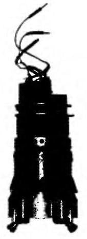
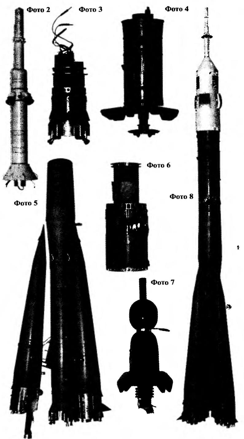
The image of the flags of the USSR and great Britain on the head fairing (photo 1) is performed through an appropriate stencil cut out of a wide tape on a paper basis. Separately painted in the appropriate tsaeta other elements of the details (nozzles, antenna). Small parts can be painted with a soft brush or by dipping, after sticking them on the ends of matches.
On the surface of the caudal compartments of the Central and blayh blocks glued (with glue “Mars”) simulated thermal protection. At their ends mounted nozzle, steering motors, valves and other elements of detailing. Also neatly mounted on the outer surfaces of all parts of the model the remaining elements of detalyami using clear 5-minute epoxy. On the finally assembled parts of the model by means of decalcomania put lines of the zones of supports and markings.
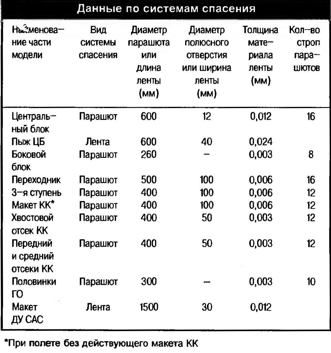
Rescue system and their installation. For all parts of the model, to which it separated in flight, made system of salvation. As a material for domes, parachute and tapes used metallizovannyh Dacron (polyethylene terephthalate) of various thicknesses, for slings, parachute take a thin nylon thread No. 30-40, and for the tether ribbon — cotton thread No. 00. They are fixed by means of thin adhesive tape according to conventional and missile modeling technology.
Ribbon tied to southeastem parts of a model shock absorbers, each of which is folded adwoa rubber thread with a diameter of 0,8—1 mm and a length of 300 mm. It is passed through a snap ring or a thread loop and zavyazat ring. Similarly attach the parachutes polaino and BB. Parachutes compartments layout KK attach the same shock absorbers using twisted metal wires made of micromoog wire with a diameter of 0.1 mm. at One end through the soldered loop they are attached to the spring rings. At their free ends made the same loop, are bonded by soldering. The same cable is used for attaching the parachute the 3rd stage. It fastened with a spring ring aernem on the frame of the 3rd stage. To its free end, where he formed a loop, is attached to the parachute via a membrane absorber. Parachutes adapter and the Central Bank through the membrane absorbers is attached to the spring rings on the plug resistant cylinder adapter and the front bulkhead of the housing of the Central Bank respectively.
Preparation of model rocket engines. Digitale 3-tier layout and KK is inserted into the split sleeve, the mouth-yavlyayut on the lathe and low speed cutting chiseled from the side of the nozzle to remove clay and obtain Roanoke end of toplica. In the prepared digital insert soloaug Tulku the top and spilling liquid epoxy compound. Then the glueing is heated with a Hairdryer.
All diagela the upper end Salaat epoxy compound. After curing tubes diately that form of command for execution of the flight demonstrations and the ejection recovery systems, drilled othersthe with a diameter of 2-2,5 mm to fuel or tracer. Then the engines fell asleep hanging aising and fireworks Zaragoza that top cover with wads of capacitor paper. It is necessary to exclude otsypana of test portions from the holes. All diately thoroughly clean the drill bit nozzles.
Weight of one set MRD for a flight in a 4-speed version — 94
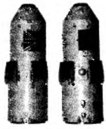
To prepare for the flight. The first operation — the application of graphite lubricant normal soft pencil on the mating frames. This will allow easy Restigouche parts of the model. Further conventional scheme laid parachutes. The tape layout DU CAC (photo 2) tightly rolled into a tube shape with a diameter of 6 mm and tape a wad of Bank — in the normal way. Then all systems of salvation wrapped in covers made of a thin fluoropolymer film clips and clothespins. In the pistons BB fall asleep linkage of gunpowder, stick with hole circles of the capacitor paper with the help of nitroblue.
The next operation is the mounting of MRD. The engines of the CB installed in the corresponding pipe UP (photo 3) and fix with pins through the holes in the tubes and the top of the engines. In the Central cavity of the upper pyrotechnic frame is filled to the linkage of gunpowder and screwed the plug. To the pins on the tubes connecting the corresponding pin and socket side of the mains, insert the compartment in the housing of the Central Bank and turn to the position and which holes coincide with the holes of the cylinders.
Digitali BB mounted on a tight fit, providing, if necessary, retrieve the tape. Engine 3rd stage (photo 4) is inserted from above TO lock the spring pin, having its ends and openings of the compartment. When flying in 4-speed the engine layout KK is mounted TO its tail section, similar to the MRD of the 3rd stage.
BB folded parachute neatly placed in a drawer and Sadagat it by click on the dummy nozzle. The emphasis of the tip is adjusted to the BB pusher of the Central Bank (photo 5), move forward, Pourciau around it and insert the piston until the end in the corresponding cylinder. Installing all blocks, checking them for alignment with the Central Bank and, if necessary, a little provorachivayut TO the Central unit, ensuring alignment. In the inner pipe to the stop of aniz insert the wad, placing Sergo him the tape, and pour a little talcum powder.
In starting the adapter socket (photo 6) insert Elektrostal, put on a tube and covered with a portion of gunpowder. Fold the stabilizer of the 3rd stage, move it up and join the step to the adapter so that the nozzle tips MRD went inside the starter Cup, and the bottom of the bulkhead steps to the end, sat on the aquatic place in the lower bulkhead of the tail section. The pins on-Board network 3-tier have to enter a socket on the housing of the adapter. The inner housing is inserted to lock the wad of paper and on it stack a parachute 3rd stage.
The slot in the base of the tube shooting of TH middle compartment layout QC (photo 7) mounted Elektrostal, dock front and middle compartments, and fastened them with pins. In pipe ejection, fall asleep ON the hitch lifting charge, close the top circle of capacitor paper and insert until it stops the balsa wad, which is a cylinder with a height of 8-10 mm. it poured a small amount of talc and closed with a cotton wad.
If you use the 4-speed variant of the flight, the parachute Bay layout KK ukladat parachutes and join the Assembly of the upper and middle, Tsekoa with postavim compartment aligning the contacts on the exterior surface thereof. In the ignition device MRD layout KK put Elektrostal, covered a portion of the powder of the pulp and a device mounted on the end of the landing cylinder.
If you use a 3-step Ariant, a fuse is not mounted and the parachutes ukladat. In this case, the parachute layout QC is placed in the inner case 3 tier on its parachute. With 2-speed option — MRD in the 3rd tier and it Electrosoul not mounted, and the junction of 3rd stage and the adapter is fixed by glue.
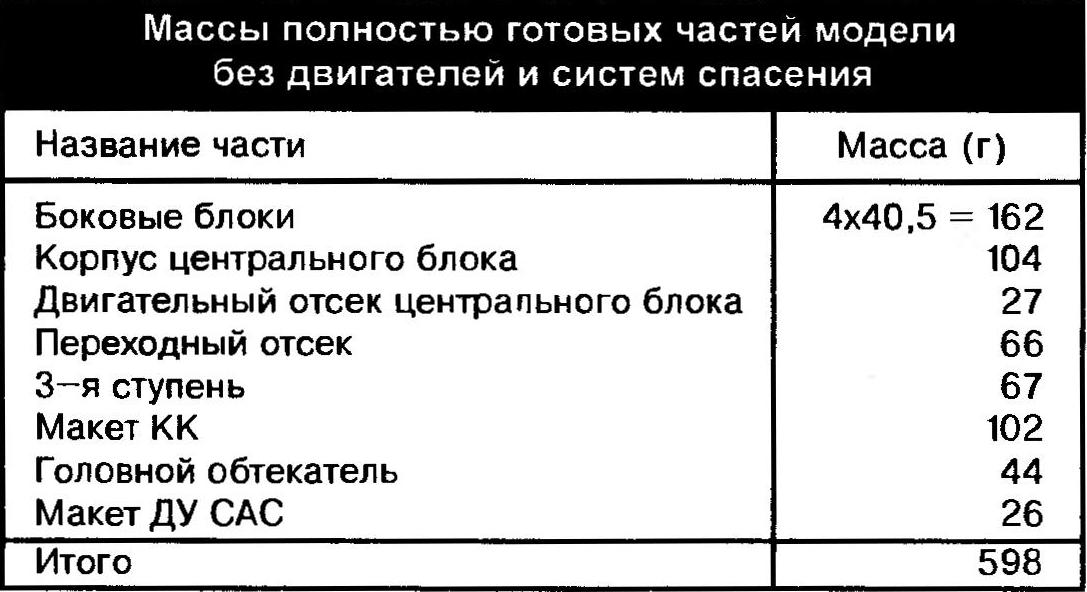
Assembled the layout of the KK pristykovyvayas to the 3rd stage, sticking the landing cylinder in the inner body of the stage, providing the articulation of the connector and the unclamping of the relay contacts. Then assembled together the KK layout, 3rd stage adapter pristykovyvayas to the package center and side blocks, placing the parachute adapter into the inner tube of the Central Bank on its parachute. While articulate side apetrosyan providing communication between the adapter and the Central Bank. Then into the phone, shooting TH place ribbon layout do the SAS and put the landing cylinder. Startea mass-models (photo 8) should be 720-740 g, and the center of gravity be located at the intersection of the cones of the Central Bank.
Next, prepare Perekrest, falling asleep under each tube and a Central sleeve, which is mounted Elektrostal, grains of gunpowder with a height of 2-3 mm, the measured size of the casings small-caliber cartridge. A model copy of the launch with a guide pin (diameter 8 and a length of 1800 mm), which is installed on the ground with a slight tilt in the wind for vertical flight. The slope of the pin depends on the wind speed. The pin put the stand under Perekrest and a movable Bush that restricts movement of the model-copy down. Their attachment to the pin to provide thrust screw.
On the stand set Perekrest, and the model-copy on the pin. A little cranking Perekrest, seeking to fuse the tube exactly ashli in the nozzle of MRD of the Central and side blocks. The model is slightly lifted and with the help of a stop record is its position where it is not based on tubes. This is necessary in order to ensure free passage of gases into the gap between the tubes and the wall of the nozzle (to avoid throwing the model at the moment of actuation of Perekrest) and increase the reliability of the ignition of the engines.
On the layout KK connect Electrosoul reset and device control circuits. With the help of latest test circuit elektrozapalom, then connect the connector side of the power supply. If everything is in order, the control unit disconnected and the connectors are fixed on the outer surface of the middle compartment of the layout with tape. Next, install the fairing by placing the parachutes of its halves into the gap between the KK layout and halves. The lower frame TH inserted in the upper frame of the 3rd stage, the joints of the halves combine, slightly pulling up the layout do the SAS. While her antennae pusher needs to get anothr and lean on the top frame. Halves fully combine, layout, do the SAS and lowered down until it is fully seated its supporting cone on the top frame of the fairing. Once again, carefully monitor the installation of Perekrest and connect it Elektrostal to control panel launch. Miniature Soyuz ready to fly.
Conclusion. Developed design and mission profile of the flight-models showed quite aisaku reliability, which allows us to recommend design solutions found for other models. This is especially true of system Department BB, which can be used in all models-copies with the design of the “package”. Also the design of the model allows to vary the options of flight, depending on the prevailing conditions of wrestling and progressively enhance the newly constructed model copy, moving from simple to more complex. Of course, for making models need not only extensive experience and qualifications, but also time. According to our statistics, to build models, in the presence of tooling and equipment, requires at least 800 workers, casoa. However, only such a model-a copy can conquer the highest place on the European and world Championships. Nevertheless, with a strong desire even young rocketmodeler may begin work on a similar model, but gradually dooda and perfecting it to achieve high sports results. We wish Alexander Left many times to adequately protect the honor of the Russian flying sports in international competitions.
Vladimir MINAKOV, honored coach of Russia,
head of the Department of technical creativity MGD(Yu)T
Recommend to read
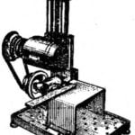 TABLE UNIVERSAL
In one of the shows can viewers was submitted to design a universal machine, designed by the engraver of the suburban town of Troitsk Y. M. Orlov. Not only a discussion of a design... FIVE “SQUARES”
One of the problems of those who live in small apartments, a small area of the kitchen. To buy good kitchen set is almost impossible, and to a random set of furniture "fit" in not...
