MODERN SCHEME

MODERN SCHEMEOdnokomnatnaya model well-earned position in the class F2A. At competitions it is hard to escape the thought that flies the same speed — they are so similar. The approved scheme is fully justified. Stretched the console closes a lot of plot cord”brake”, and the plot is moving with the greatest speed and therefore creating a short in the normal wing the greatest resistance. Other model parameters are chosen in a practical way and provide optimum characteristics of stability and controllability. However odnokomnatnoj the scheme has a distinctive shortcoming: if the engine stops the model immediately sharply losing altitude. Struggled with it, inserting the elements of the external console. They compensated for the increase in lift force of the left wing, arising from blasting his air screw. Eventually had to abandon for more, reducing the speed of the wing, opposed “Norov” speed skill of the athlete.
The pros and cons odnokomnatnoj scheme we have tried to take into account when designing the model of the transition type. It is designed for modelers who have mastered the basics and is going to seriously speed championship class. But as practice showed, at once to step from “uchebok” to the high-end models is very difficult. Transitional built in accordance with modern requirements for aerodynamics, then when you accelerated the engine easily allows you to execute the standard athlete I discharge!
 
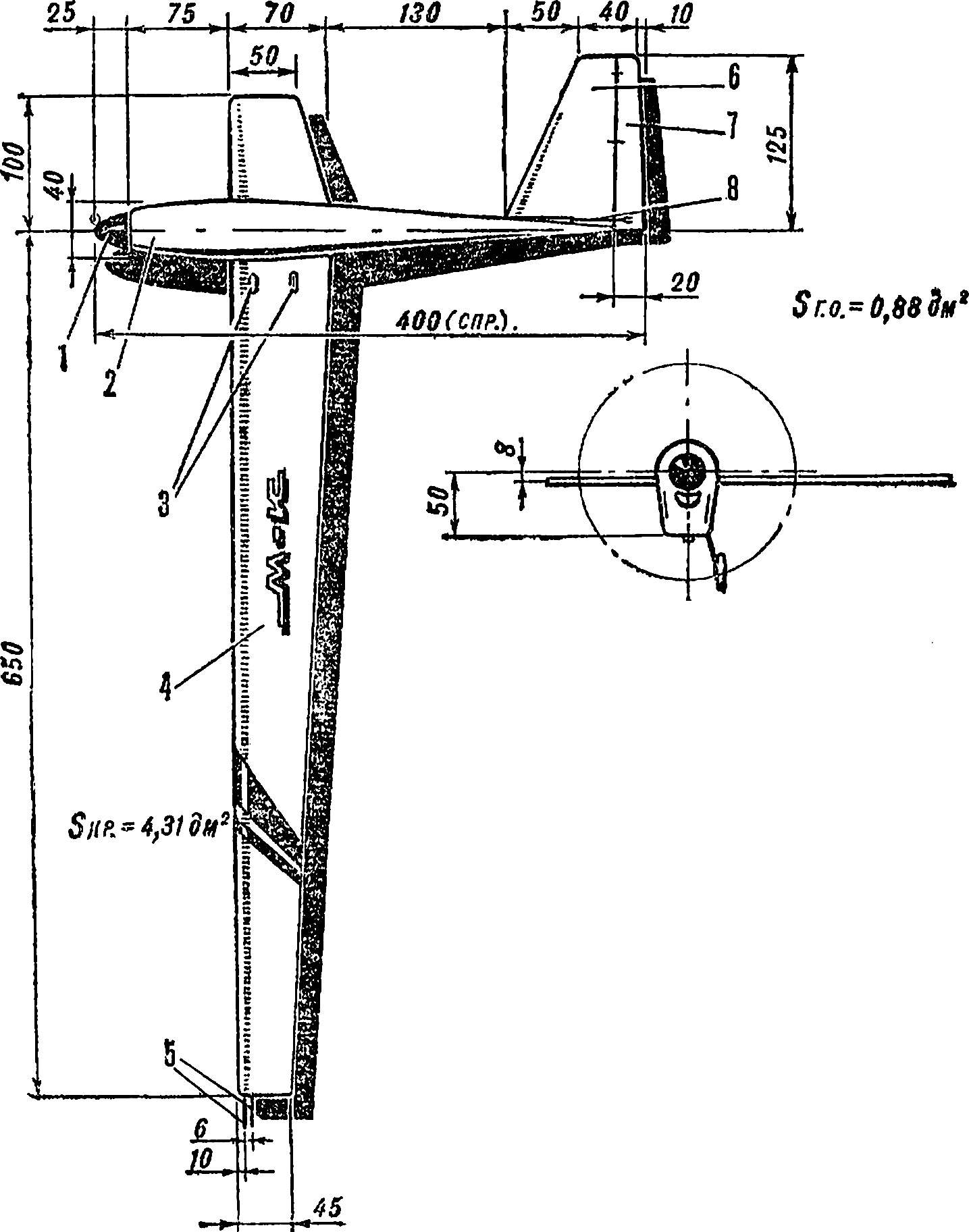
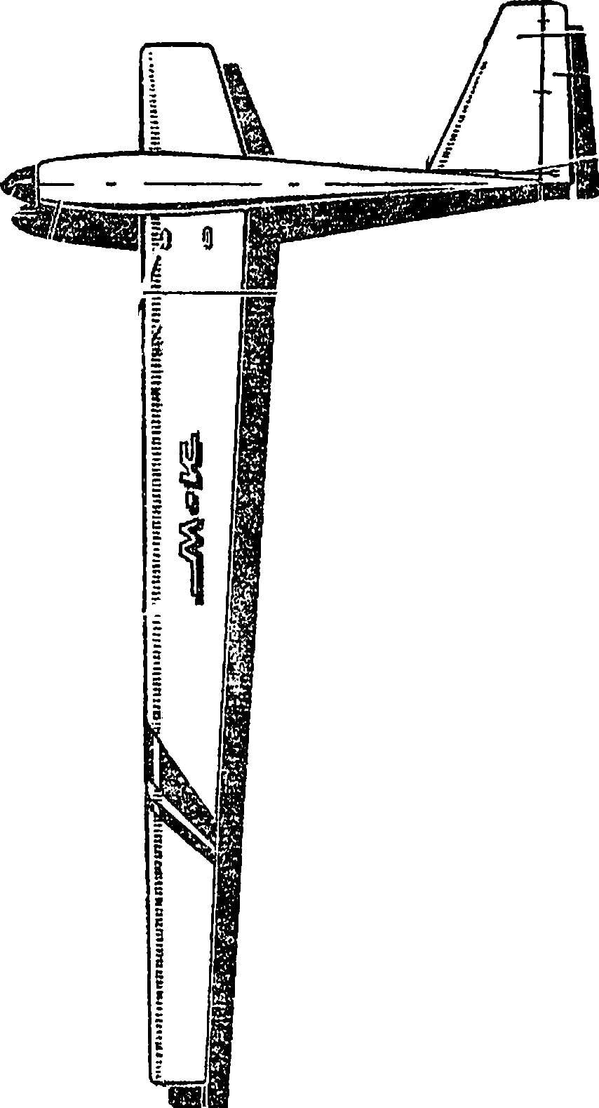
Thus, the scheme — adekanola, to facilitate the training introduced a small right half-plane. And to make the building available to each Modeler, we designed a high-speed solid wood, rejecting the use of thin aluminum for the wing, the magnesium alloy machined motor and other scarce materials. In anticipation of possible failure when training the model is designed collapsible. Because, as a rule, even after the failed launches of repair accounts for only one item. And the work on the apparatus, consisting of three main components, simpler and faster to manufacture such high-speed takes no more than two to three weeks of group classes.
 
Fig. 1. Control line speed model airplane.
Fig. 1. Control line speed model airplane:
1 — spinner, 2 — body, 3 — window approach to the carabiners hanging cord, 4 — wing, 5 — kordovye thread, 6 — stabilizer, 7 — Elevator, 8 — pull rudder.
The most important element of the design for the wing. It is experiencing heavy loads, not only during the flight at high speed, but rough landings sometimes seen and experienced athletes. The basis of the power scheme of the wing serves as a rigid carrier covering from millimeter plywood. This console is not heavier metal, bent from duralumin with a thickness of 0.3 mm. It is inferior to the latter in hardness, but more tenacious.
 
The requirements for absence of twist in the wing meets the highest. Therefore, when assembling the wing suggest to use the technology we have developed. Primarily on the bottom casing is mounted on the glue front edge, sostragivaja the profile of the future console. Then a sheet of plywood is processed on the rear tail section for joining with the top sheet. Further Assembly operation — only “stocks”. He represents the calibrated thickness strips, with a minimum thickness of 4 mm, nailed to the flat surface of the Board base. The slats are fixed so that they overlapped the contour of the edges of the wings 1-2 mm.
 
Posting on the staple lower sheet, it is glued internal components and mount the control unit Assembly, and then glued the top part of the skin. The parts indicated in figure 3, positions 3, 15, 18, need to be made of hornbeam. This is the most solid material, it better resists crushes loads in the attachment points of the wing to the fuselage. Only in an extreme case, you can use beech or birch.
 
Work on the fuselage begins with the manufacture of its basic element, a motor. After a recess to facilitate Windows and cutting a space for the engine in it sealed threaded fungi for mounting all detachable elements. Then glued grooved plate consisting of a main and two front parts. Between the wing and the stabilizer can be facilitated, increasing the thickness of the walls in this place up to 3 mm. do Not forget to hollow out the channel under the thrust of an Elevator, annoy to do this will fail.
 
Fig. 2. The design of the fuselage.
Fig. 2. The design of the fuselage:
1 — Kok-nut (D16T), 2 — statinary fairing of the propeller (D16T), 3 — upper cowl (lime, lightening), 4 — front seal (lip thickness 8 mm), 5 — engine CSTOM-2,5 TO 6 — main panel (lip thickness 8 mm, to ease in the area between the wing and the stabilizer, the hollow groove for traction Elevator), 7 — wing 8 — fuel tank (plate 0.3 mm thick), 9 — wall of the fairing (Linden), 10 — pin fixing the rear part of the fairing (bamboo, gluing in the tail fairing), 11 — motor mount (plywood 8 mm thickness, cut into the box below the crankcase, to alleviate by cutting through the window), 12 — tail fairing (Linden), 13 — the crutch 14 — regulator 15 — horn 16 — Elevator 17 — the lower wall of the fairing (plywood with a thickness of 1-1,5 mm), 18 — a wall-screen of the diversion of cooling air and exhaust (plywood with a thickness of 1 mm), 19 — fairing (Linden), 20 — threaded sockets for screws of fastening of a fairing, 21 — tube drainage or pressurization tank, 22 — supply pipe, 23 — wing mounting screws and the tank 24 to the rear wing mount screws and the tank 25 is a threaded socket fastening of the stabilizer, a 26 — fairing exit traction, 27 — claw termination of thrust steering.
 
Fig. 3. The design of the wing.
Fig. 3. Wing design:
1 — external ending (Linden), 2 — front edge (birch), 3 — front lining (hornbeam), 4 — Polonnaruwa (birch), 5 rocking (D16T thickness of 1.5 mm), 6 — lower sheathing (plywood thickness 0,8—1 mm), 7 — upper sheathing (plywood thickness 0,8—1 mm), 8 — the walls of the channels for the cords (lip thickness 1-1. 5 mm, the height of the two front 4 mm, rear — 3 and 2 mm), 9 Corda Ø 0.4 mm, 10 — tapered tube input cord into the wing, 11 — internal ending (lime), 12 — glue seam joining securenym wedge wing panels, 13 — finishing coating (Mylar film on the glue “Moment” or micuenta paper on parquet lacquer), 14 — window approach to the carabiner hitch cord, 15 — back lining (hornbeam), 16 — tubular clamp carabiner (tapered thin-walled brass tube) 17 — desire (OVS wire Ø 0,6—0,7 mm) 18 — bracket rocking (hornbeam), 19 — axis rocking (OVS wire Ø 3 mm), 20 — incorporation of cachacinha the end of the pull rod (a thick-walled brass tube, compressed).
The bonded fuselage panels are installed fairings, traction and lightweight top and tail. Then fit the cowl-fairing it is mounted wall, diverting the hot gas flow from the tank. To seal the seam between the wing and fuselage during Assembly, there will be a foam thickness of 1 mm. Smenas “zero” the tightening torque of the screws, it will not affect the accuracy of the installation of the wing, but it is reliably prevents the cavity of the wing from falling oil.
 
Do not be surprised still not a word about the tail. It start only after the completion of all other items up to their finishing and painting. Having assembled the model without stabilizer, hung midway between the points of attachment of the horizontal tail loads in such a way that the center of gravity was located at 5 mm from the front edge of the wing. The goods are weighed and, based on obtained values, ask lots of stabilizer (given its construction), the horn of the Elevator, the rudder, hinges-hinges and screws along with a crutch. With a significant stock weight of the stabilizer is cut out from plywood with a thickness of about 2 mm. to Reduce the mass relief of the plywood blanks or upgrade to a composite version, wrap the Mylar film. The thickness of the tail in this case should be brought up to 3-4 mm. it Should be noted that integrally cast with the stabilizer of such a weakened structure would be inapplicable, the connector also allows you to get rid of the loading nose of the model through the use of is not very durable, but also easily recoverable or repeatable parts.
 
Chassis — of any type, up to single column. To install the best engine head. Usually an extra load on the engine try to avoid, here, when the inverted motor, the stand is extremely short and therefore the load from it and the increase in resistance is minimal. This significantly simplifies launch of the model. Someone who has never piloted a high-speed, it is useful to temporarily install the second wheel on the inside of the right wingtip.
 
Main features of the model
 
Wingspan, mm: 750
 
Length, mm: 400
 
The area of bearing design, DM2: 5,19
 
Dry weight, g: 410
 
Specific load, g/DM2: 79
 
Engine capacity, cm3: 2,5

 
V. KIBETS, head of airmodelling mug club “Iskatel”, Moscow

Recommend to read

  • LITTLE MICRO-CAR “BUDDY”LITTLE MICRO-CAR “BUDDY”
    Little micro-car "Buddy" machine... for kids. It was created in a laboratory experimental simulation and design Club for young technicians Novosibirsk Akademgorodok. Despite its small...
  • THE BIT WITH “HAT”THE BIT WITH “HAT”
    A tool with a wooden handle easier and more enjoyable to work with. Therefore, as a rule, the old masters do not recognize the replace them with plastic. However, when attacks on them...