We have to admit that progress in this area is enormous. Engine power for a short time increased in 2-3 times, which gave a noticeable speed boost — sometimes the models run faster than the real record of the courts. But do not forget that the possibilities of improvement and devices themselves are far from exhausted.
We present model development is different from traditional it scheme hydroplane. Unusual location of the engine cylinder, and the unusual shape of the entire model. Some parts of the new high-speed sophisticated. For example, the original solution nasal redan allows you to change the angle of attack depending on specific conditions-in the working conditions of the plant. For this model you can recommend a manufacturer of several plug-in steps with different shape planing surface and at practice to pick up samples with the best starting and running properties.
A slightly more complicated design was chosen for the proposed model and the bracket propeller shaft. You can now adjust the distance between redan and aft axis of the propeller and the inclination of the shaft relative to the surface of the water. The engine in the new unit is mounted behind the rear wall of the housing. It should be noted that most of the athletes belong to this mounting method with caution. However, numerous experiments have shown that the installation of the engine on the rear of the reliable and does not reduce maximum power.
Of the two built gliders first vydalblivaetsya of lime. Of course, it wasn’t easy, and strength is significantly lightweight “shells” turned out to be low. Better get a second model of fiberglass and epoxy resin.
Fig. 1. Model Cordoba glider with the propeller:
1 — exhaust, 2 — enter the starting belt, 3 — window, power-up glow plug, 4 — the screw of fastening of a cover of matousek, 5 — screw adjustment of the angle of attack of the front of the redan, 6 — removable adjustable redan, 7 — fuel tank 8 — engine, 9 — self-aligning bearing with waterproof seal, 10 — stern tube wells, 11 — nut-fixing screw to adjust the angle of attack of the redan, 12 — hard disk 13 — finger redan, 14 — filler, compartment flooding, 15 — watertight bulkhead 16 — bracket of the propeller to the frame.
Fig. 2. Correct (top) and incorrect (bottom) position of the glider during the race at different heights of the Central tower. The right shows the model of the new scheme, the left — traditional.
Fig. 3. Engine mount and fuel tank.
Blank for veclachi the plastic casing was not used — was used a novel method of manufacture of shells of complex shape. The engine Assembly with exhaust resonance tube installed on the engine mount, it is attached and the fuel tank. Whole tillers was wrapped in plastic wrap and were daubed with clay, which was given the shape of the future model.
After complete curing of fiberglass veclachi the engine compartment cover cut out and tillers removed from the body. Bo time of this operation for the complete removal of clay is sufficient to heat Vileika to 80-100°. In the future is mounting hardware and trim model.
Since the model can be constructed under any existing engine, the specific amount of matousek not listed. However, in the selection of the motor should be preferred to samples from the distribution of intake of the mixture of hollow crankshaft. Foam buoyancy blocks provide positive buoyancy fixed the glider, the location of cooling the engine intake air and exhaust exit on the top side of the enclosure prevents the ingress of water into the engine compartment.
On the first model motor mount is glued under engine plate. But the inconvenience of operation (difficult Assembly and disassembly of motor) forced to abandon this design. For mounting the motor was made from duralumin frame on which both are mounted and the fuel tank schematic “single-chamber drinker”.
It should be noted that the proposed horizontal arrangement of the motor position stabilizes several models during a race. Since the centre of gravity tends to take place on the same axis with cord thread, then deleting it from the point of connection cord straps elastic tie increases the leveling force generated by the movement of the glider and rising with increasing speed. Adjustment of the model on the bridle has its own characteristics and must be performed again by changing the height of the Central tower aquadrome. Because it is according to the rules of the competition can be set within a wide range. If the model is adjusted to a certain height of the riser, and the launch is carried out, for example, when enlarged, it causes separation of the internal float with a usual glider. The result will be increased resistance to the movement speed, at the same time the slope of the model will change the working conditions of the propeller for the worse. The model is devoid of floats, to a much lesser extent affected by inaccuracies in the height adjustment of the riser. However, it requires adjustment of this height.
R and S. 4. Adjustment of the position of the axis of the propeller shaft.
R and S. 5. The appearance of the vertical moment if the axis of the propeller with the center of gravity of the model.
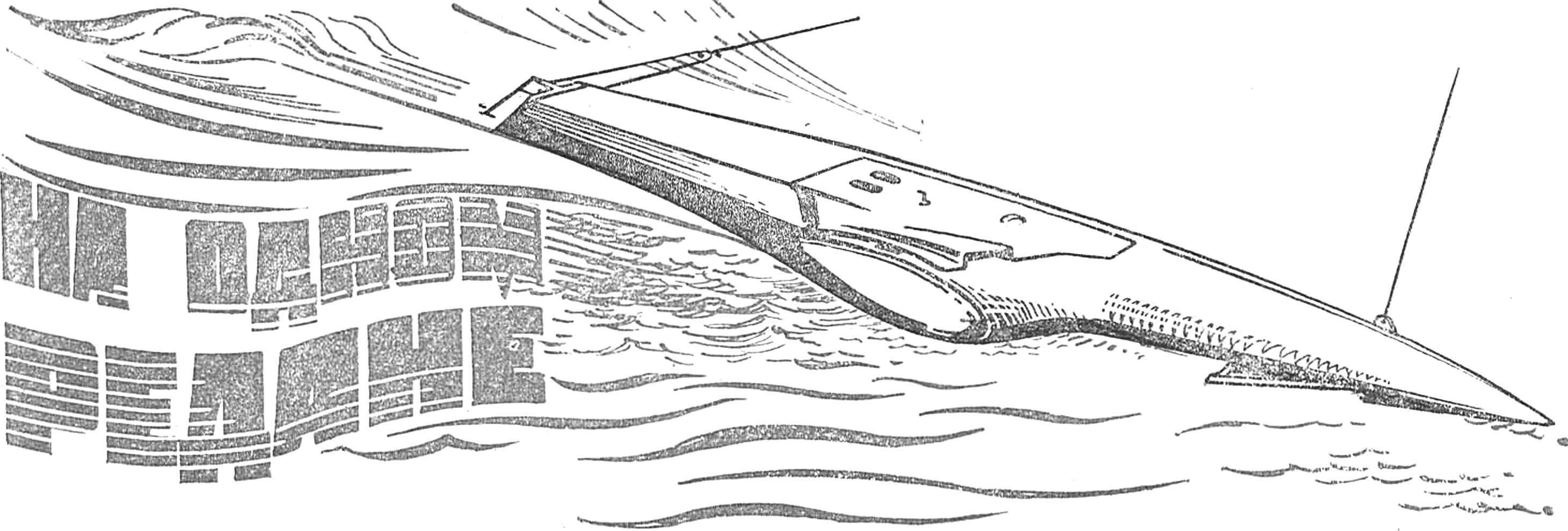
Fig. 6. Wrapping around float with traditional contours (left), and body with a longitudinal stepped sponsons (on the right — three stages in the output mode).
The need to set the position of the axis of the propeller at altitude due to the changes in nasal height adjustable redan. As the length of intermediate propeller shaft is constant, to compensate for changes of length is a set of washers, swap the sock with the front prop shaft on the rear and Vice versa.
Bracket design allows you to adjust the position of the axis of rotation of the screw relative to the center of gravity of the machine. To some extent it helps to increase the stability of high-speed hydroplane in the various States of the surface of the water.
V. KALMYKOV, Komsomolsk, Poltava region.
Recommend to read THE ROD — CHUTE … Fall — during fall and rainy weather — wet leaves quickly clog all the drains from roofs and especially gutters. To prevent this from happening and did not have those constantly cleaned,... THE PROJECT-MODEL-CAR Design and manufacture of midget cars is one of the popular directions of technical creativity. This can be judged by the growing number of automodular presented at various technical... 
 Continuous improvement of engines and circuits cord boat allows them to develop increasingly high speed. Along with the design changes and the appearance of the apparatus Particularly dramatic changes have undergone recent high-speed model with aerodigestive. But in the class A1 scheme over many years remains, essentially, unchanged. Most athletes prefer to speak with a reliable traditional pattern: vertical location of the engine at the main building, equipped with two additional floats. The most careful attention is paid to Moto installations.