the  (the End. The beginning see in # 9-11)
SERVOS
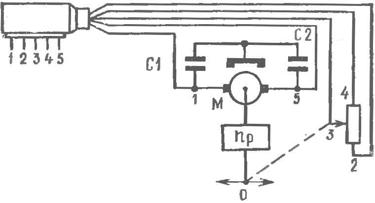
In the “Radiopop” is applied to the DC motors with independent excitation (permanent magnet) type DP-1-26, DP-1-13 with modified brushes and DP-1-26 *rewound to the working voltage of 4.5—5 V. replace the carbon brushes on metal, made of thin wires, gives the opportunity to improve the performance of engines to reduce static moment of resistance, to IMPROVE efficiency, etc. the Electric circuit actuating mechanism — figure 1.
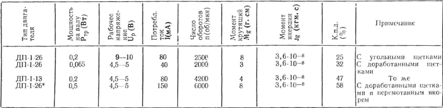
Main engine parameters are presented in table 1, and their performance — in the figures 2-5.

Fig. 1. The electrical circuit of the steering machine.
Servo motor and gear ratio selected from the conditions for the transfer the required power to the load (under load means the force required to drive the rudder and the height of the ailerons, the mechanism of release and retraction, to control the engine).
TABLE 1

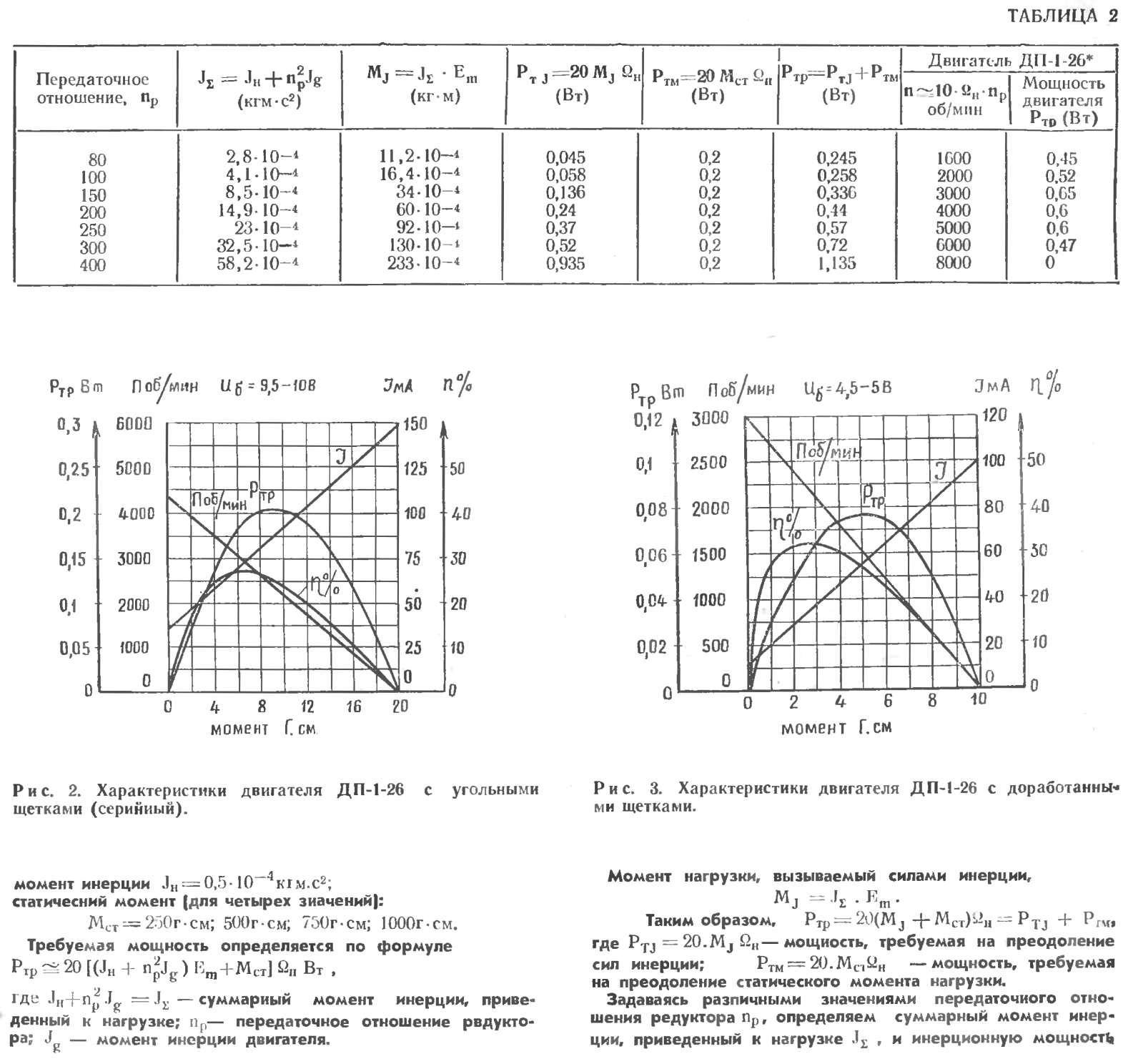
PTJ. Power of the selected engine type and full load power of RGR is determined depending on the gear ratio of the reducer according to table 2, designed for engine DP-1-26*— when MST = 500 g·cm similarly the calculation for other values of MSt.
Curves of power load and engine DP-1-26*DP-1-13 depending on the gear ratio reducer is shown in figure 6. The graph shows that the maximum excess engine power DP-1-26 * over the load power (when MST = 1000 g·cm) is between 90 and 200. For engine DP-1-13 maximum excess power over the load power (for M St= 250 g·cm) is between 60 and 110. Thus, any gear ratio within this range provides adequate power supply for proper functioning of the steering machine, installed on Board a radio controlled model. Guided by the above considerations, the gear ratio is chosen equal to np = 136-140, which, as studies have shown that good agreement with parameters of the amplifier and the load.
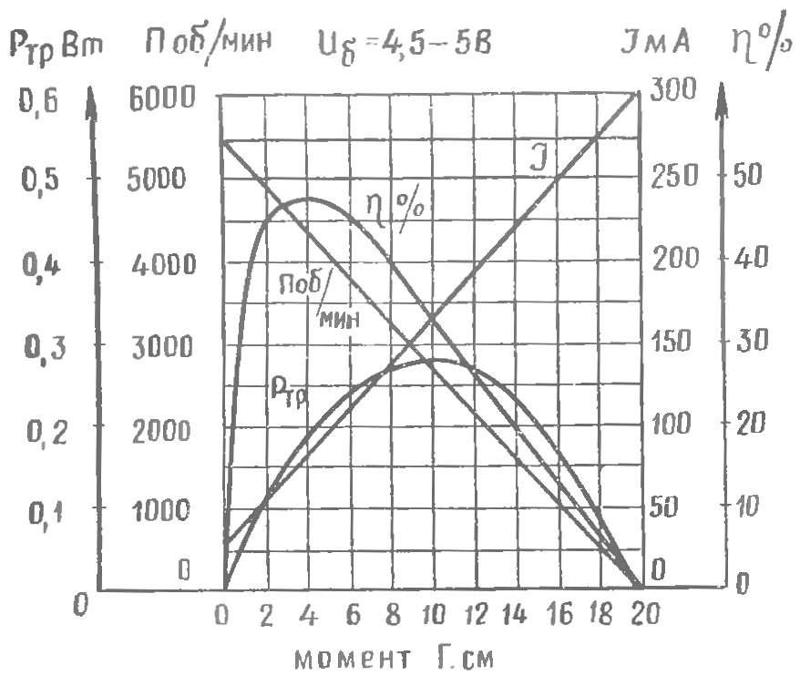
Fig. 4. Engine performance DP-1-13 with modified brushes.
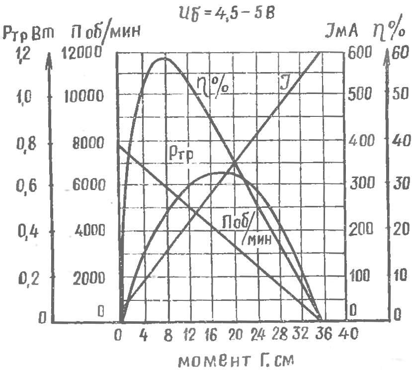
Fig. 5. Engine performance DP-1-26* with rewound armature and modified brushes.
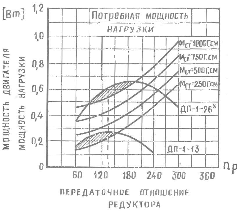
Fig. 6. Graph to determine the optimal gear ratio of the reducer.
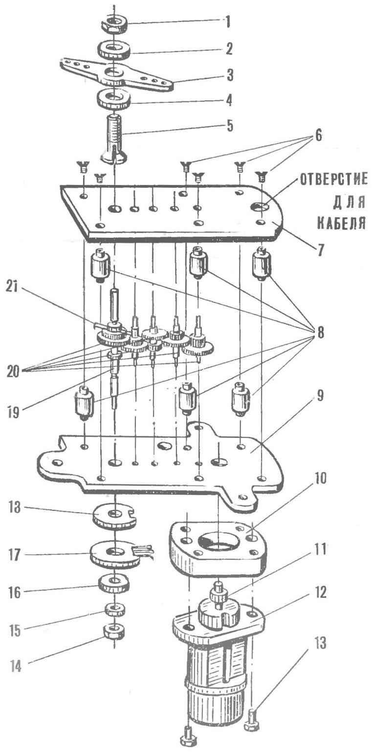
Fig. 7. Device steering servos:
1 — nut (PT. 45); 2 — washer (D16T); 3 — rocking chair (the PCB); 4 — washer (D16T); 5 — Tsang (Д1СТ); 6 — screw M2,5; 7 upper Board (PCB); 8 — (D16T); 9 — bottom Board (PCB); 10 — spacer (PCB); 11 — pinion 12 — motor; 13 — bolt; 14 — nut; 15 — washer (brass); 16 — the potentiometer; 17 — feedback potentiometer: 18 — washer (Micarta); 19 — output shaft gear (St. 45), 20 — gear reducer; 21 — stop (PT. 45).
The device steering the car in figure 7. Adjustment it is to ensure smooth rotation of the reducer and potentiometer feedback without motor. Particular attention is paid to secure contact of the potentiometer and linear resistance depending on the angle of rotation of the output shaft of the gearbox. Then, after the installation of the electric motor, and finally check the ANTOR group has of the gearbox.
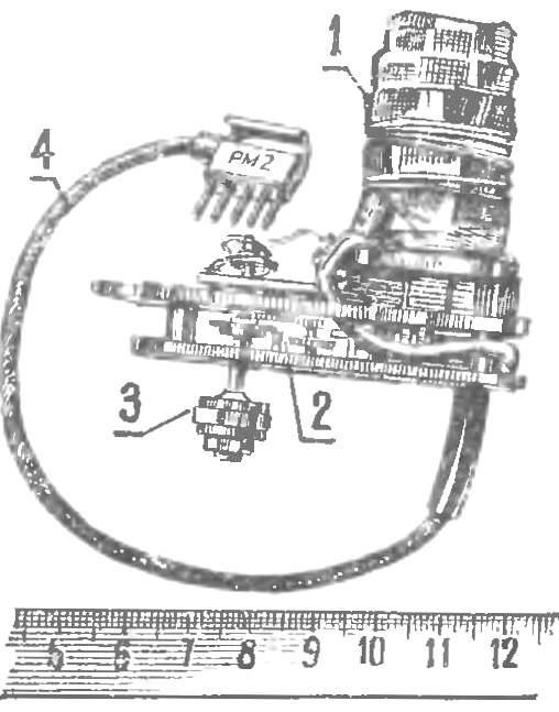
Fig. 8. The appearance of the steering machine:
1 — electric motor; 2 — reducer gear; 3 — the output shaft of the gearbox; 4 power cable connector
Correctly assembled the machine (Fig. 8) must have a minimum value, the backlash output shaft. Remember that servos mounted on Board models, subject to a fairly significant vibration overload. Therefore, the mechanical strength and the attenuation servos are strict requirements. The unreliability of the contact in purpose of the feedback or the armature of the motor in terms of vibration can cause interference, disrupting the work of radio receiver.
On the issues raised in the article, we recommend reading the following books:
1. Verebryusov I. A., Simultaneous transfer and tracking system. L., Sudpromgiz, 1954.
2. “the Technique of transmission of the measurement results on the radio”. A collection of translations by radio telemetry. M, Voenizdat, 1955.
3. Transel George. J., Reference book on the art of automatic control. The translation from English. M., Znanie, 1962.
4. Belyaev N. I., Nagorskaya V. D., the Choice of motor and gear tracking systems. M., “Engineering”, 1972.
5. Petrov I. B., Electric drive control systems of aircraft. M., “Engineering”. 1973.
G. OKHOTNIKOV
Recommend to read
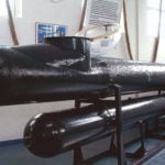 THE GERMAN-CONTROLLED TORPEDOES
The development of guided torpedoes to sabotage units of the German fleet was conducted in parallel with the creation of the midget submarines. The first model of this weapon was...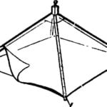 “UMBRELLA”-GREENHOUSE
On the merits of a greenhouses can not speak: they become part of the Arsenal collective and individual farms. With the development of horticultural cooperatives such light-transparent...
