Fuselage:
1 — nasal boss (Linden), 2 — bow frame (plywood, s), 3 — notched stringer “cockpit” (dugout detail of lime), 4 — locking trim cover (plywood, s1,5), 5 cover (plywood, s1), 6 — Klondike solitaire (plywood, s), 7, 13 — power frames (plywood, B2), 8 — panel bulkhead (plywood, s), 9 — towing hook, 10 — the cradle of the tow hook (plywood, 52…3), 11 — cradle servos (team detail of Board and birch plywood linings, are shown in a single figure by hatching), 12 — underwing stringer (Linden or pine; to connect with stringer rear fuselage gluing “on us”), 14 — rear gusset plate (plywood, s3), 15 — stringers (pine, Reiki 3×3), 16, 18 and support frames (foam PVC, s4), 17 — sheathing panels (plywood, s1), 19 — back pin (beech pin 5), 20 — postepisiotomy frame (foam PVC, s4), 21 Kil (Linden, plate, s…S,5), 22 — frame rudder (team detail: pine slats 3,5×1,5 and 3,5×3,5, and fake plates, s,5), 23 resistant strap cradle of stabilizer (lime rail 4×4), 24 — wing pins (pins 6 beech), 25 — screw M2 cover 26 — Board (plywood, s1). The types of frames are shown holes for holding shells Bohdanovych pull rudders. 6), 25 — screw M2 cover 26 — Board (plywood, s1). The types of frames are shown holes for holding shells Bohdanovych pull rudders.
Wing:
I — solitaire (Fanari. s2), 2 — the ending (fake plate, s5), 3 — longeron (team detail: pine rack 6×2,5 — bottom shelf and 6×4 — top; plywood, s2, — a wall between the ribs on the inner polarisman and foam, s2, — wall to the rest of the wing), 4 — rib (fake plate, s1,5…2), 5 — Polonnaruwa (fake plate, s1,5), 6 — the leading edge (rake pine 6×6), 7 — lining (plywood, s1,5), 8 — sided casing of the root partition (plywood, s1) 9 — root rib (ply, s1), 10 — axis of the connecting pins 11 — boss with a hook for a rubber loop tie polacrilin, 12 — rear flange (fake rake 25×4). The first two rib root portion are made of plywood with thickness of 1.5 mm with the understatement of the circuit is 1.2 mm.
,
Sections of the supporting planes:
And the root section of wing, B — intermediate section of the wing In the root section of a stabilizer, G — intermediate section of the stabilizer with the Elevator.
Stabilizer with Elevator:
1 – solitaire (plywood, 2— ending(fake plate, z), 3 — longeron (team detail: pine slats 4×2 — top and bottom shelves and foam, s2, — wall, installed in the Central three sections of the frame), 4 — rib (Linden, s1 … 1,3), 5 — Polonnaruwa (Linden, s1), 6 — sided sheathing (plywood, s1), 7 — front flange (lime rail 4×4), 8 — loop suspension steering, 9 — simplified auxiliary loop, 10 — rear flange (pine rack 4×4) 11 — trim the edges (lime), 12 — bracket synchronization of the movement of the rudder (wire OVS 2), 13 — filament winding of tubular mounting hinge bracket (overlay before gluing parts 11), 14 — frame of the Elevator (team detail of NZ pine slats, and fake ribs).
Tow hook from dural “brand”.
Between the finished side walls of the fuselage are glued two power frame, and then consecutively and all tail. At this stage it is necessary to properly assess the straightness of the lower fuselage, the Assembly of which can be done on a flat Board-the stocks that will rule out a possible twist (only have to control the straightness of the longitudinal axis of the fuselage, but it’s easy).
The next step — gluing of rails, pads, tool trays and other small parts, as well as the sidewalls in the bow to the front bulkhead and securing it. After installing the “cabin” shaped stringers, the frame trimmed and the installation of the upper and lower plywood panels. At this stage of Assembly, keel not fixed yet, for it left only a groove in the rear fuselage. The fact that the selection of the design of the keel and its weight can change the alignment of the whole model without the use of ballast weights. But bodanova traction drive rudders must be mounted before the imposition of the upper and lower casings, and later to do not succeed.
Assembled the fuselage is sanded with abrasive paper and varnished several times. The perfect surface can be achieved obcanov the fuselage macalintal paper, otakarova. –
gap nitropaints. Ready, it needs to have a mass of not more than 210 g (plywood shell elements in total weigh about 100 Gauss, so the reserves are). Mounted on-Board equipment radio and are glued beech pins for the rubber rings attaching the wing and stabilizer.
Now wing. It will need a quality pine slats (for the frame) and lime blanks (for back edges). The spar is best made from a dense grained wood, and the front edge of the suit and the lighter varieties. Ribs can be obtained by any convenient way: to treat them in a pack or separately, either pre-cut profiled billet in the form of separate sections of the wing band saw or wirelesscom. In each case, required a perfect fit grooves under the edge and spars. The precision of the observance of the contours may not be too high — wing with this profile is it will not worsen.
The frames are mounted polycrylic after mutual adjustment of parts on the Board-the slipway. Binder — still the same epoxy resin. When assembling front under portion of the rear edge (at this stage it must already conform to the wing profile) and under the bottom shelf of the spar enclose the support rail. Waiting for the resin curing, the frames removed from building and neatly trimmed.
Now it is useful to compare the strength of bonding “epoxy” and Amalita or PVA. The comparison is clearly in favor of the former.
The wing ribs do not from 1 mm plywood, as is customary in such models, and fake plates. The latter is much tougher, lighter (its density is twice less than that of plywood), and, most importantly, the increased thickness and porosity allows the wood much safer to stick together with other elements of the frame. In addition, such ribs and the soft wing skin holds much better! It is recommended that before assembling the frames polycrylic to sort the rib, placing the thickest and most dense closer to the root zones of the wing, and thin and light — ends. The final operation — Assembly of small parts, plywood skins, reinforcements of the ribs and linings of the root ribs.
Checking connectivity polycrylic connecting pins, proceed to the wing skin. You can certainly go the traditional way and to fit the supporting plane macalintal paper on Amalia, duplicating the skin on the forehead to the spar. However, there are more modern method based on overlaying a sublayer of conventional Mylar film with glue BF-2, the “Moment” or N-88. However, this technology is suitable only in the case if you have experience with film. Advantages of the wing with Mylar sublayer is undeniable — it is less affected by temporal pubdom less sensitive to humidity, and its duplicate plating is more resistant to punctures and holes. The only downside is the inconvenience of repair in the case of using elastic glues “Moment” or N-88, which are very difficult to clean off of the frame. In any case, on top of the Mylar sublayer impose the covering of mcalenney paper Amalita. It gives the required wing torsional rigidity and provides the required surface roughness (with perfectly smooth skin model flies much worse, especially in calm weather).
The weight of the wing ribs is about 100 g, and all parts a set of longitudinal rails. So to meet the 300 g including connection pins polycrylic (front is made of wire, allied with a diameter of 3.5…4 mm and has a length of 250 mm; rear — OVS with a diameter of 2 mm and a length of 110 mm), not too difficult.
With careful Assembly and maintenance of the technology covering the wing is completely straight, without a leash, and in a negative twist on the end zones are not needed. By the way, this twist may partially substitute for trimming the rear edge shown on the drawings. The shank of the profile near the wingtips slightly raised. But if there are doubts about the manufacturing quality of the wing, before plating, it is useful to ask him a uniform negative twist in the range of 1.5…2″ (counting the wingtips relative to the root rib).
Stabilizer, and elevators, according to the scheme similar to the wing, and the Assembly of these elements in special explanations does not need.
Preparing all the nodes of the airframe and having fully completed their finish, carry out a test Assembly of the model, including installation of onboard equipment. In this case, the mounting area of the keel are placed balance weights, ensuring specified on the drawings alignment, and depending on their masses, the decision on the construction of the keel. Installing it in place and ends the work on the glider.
Item weight the mass of the model is as follows: side a part of the apparatus 300 g, wing Assembly — 300 g, the fuselage with keel — 250 g, the stabilizer with rudder and hinges — 50, Retained the provision for losses related to colour (100 g), and “jewelry” (50 g).
If you want to create a lighter airframe, you can pick up the equipment easy, abandoning the weight of the reserves and apply the balsa rib is 3 mm thick instead of lime (together with the replacement of the wing leading edges on the balsa will give an additional gain in 70…80 g). If you need to lighten the airframe to the limit, it should eliminate some of the paper covering the wing and stabilizer overlay on top of the Mylar film, in the area from the spar to the rear edge, it is important to provide a certain surface roughness of the supporting planes only at their forward parts.
Of course, you can go on celebarty design scheme of the fuselage. This will give a considerable gain in weight, especially when you consider that 1 mm plywood weighs as much as the same balsa plate with a thickness of about 6 mm. But it seems that this technique is more suitable for… such a training type glider is no longer needed. For beginners, only mastering the basics of radiobiology, much more important than the overall strength of the fuselage and its ability to protect the radio equipment in numerous extreme situations. Well, the fuselage is stronger plywood, assembled on epoxy, simply no.
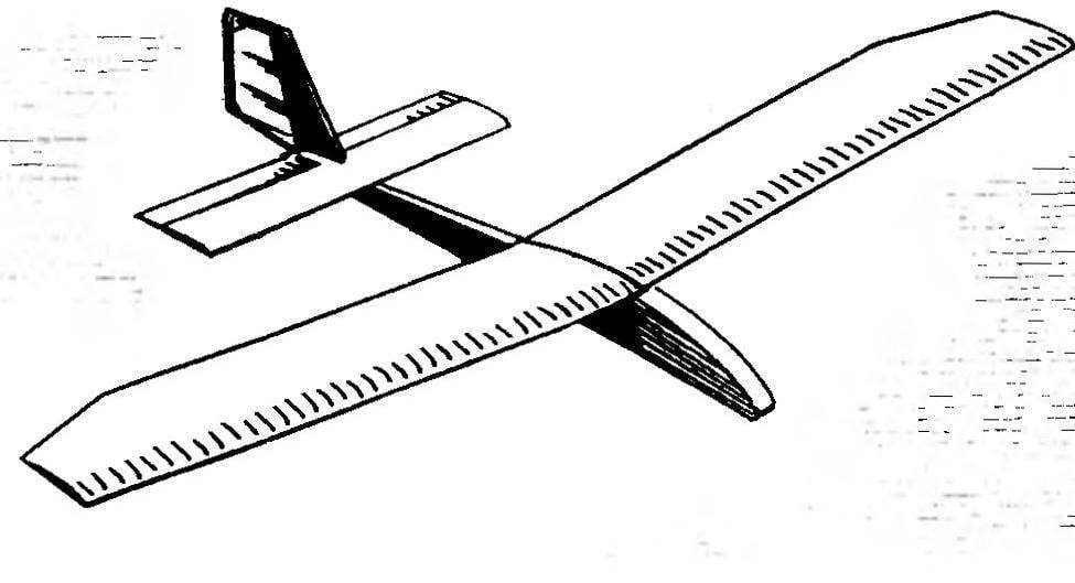
Latest control the overall geometry of the model, its balancing and flying! Note that this glider is very well behaved when towing on the guard rails of any length, up to 200 m without any problems picking up the full height even with the lightest wind.
V. GORYUNOV, master of sports
Recommend to read ANCHOR — FROM ANCIENT TIMES TO THE PRESENT DAY Oddly enough, but we tend to think of Ancient Rus agrarian power, traded mainly salt, hemp, wax, fur goods, linen. Meanwhile our ancestors were taken abroad and iron, and iron, famous... KEY TO START! — Key to start! — Attention, start! The model is slightly raised on the rails, then picking up speed, quickly disappeared in the blue sky. And the starter has already...