
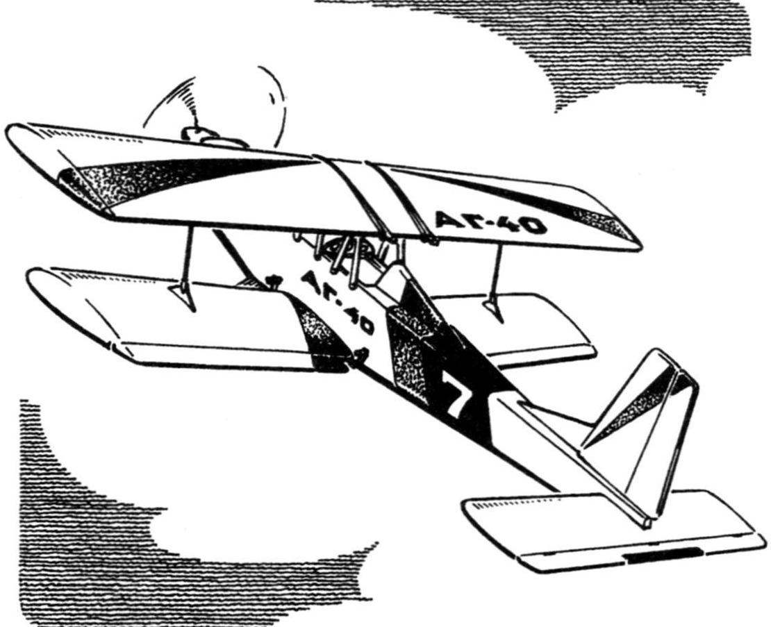
 The desire to build a model of a biplane under the existing engine MDS-6,5 KU initially led to the search for analogues. View magazines and catalogs helped to decide what I would like to see a future model. Original design prototype was a biplane DUO 40 of the company Graupner. The outline of this plane was simple and cute. Now it remained only to consider the design of the airplane.
The main materials to build aircraft with steel foam, balsa and birch plywood. Power circuit – typical for modern RC models free, Nacimiento class.
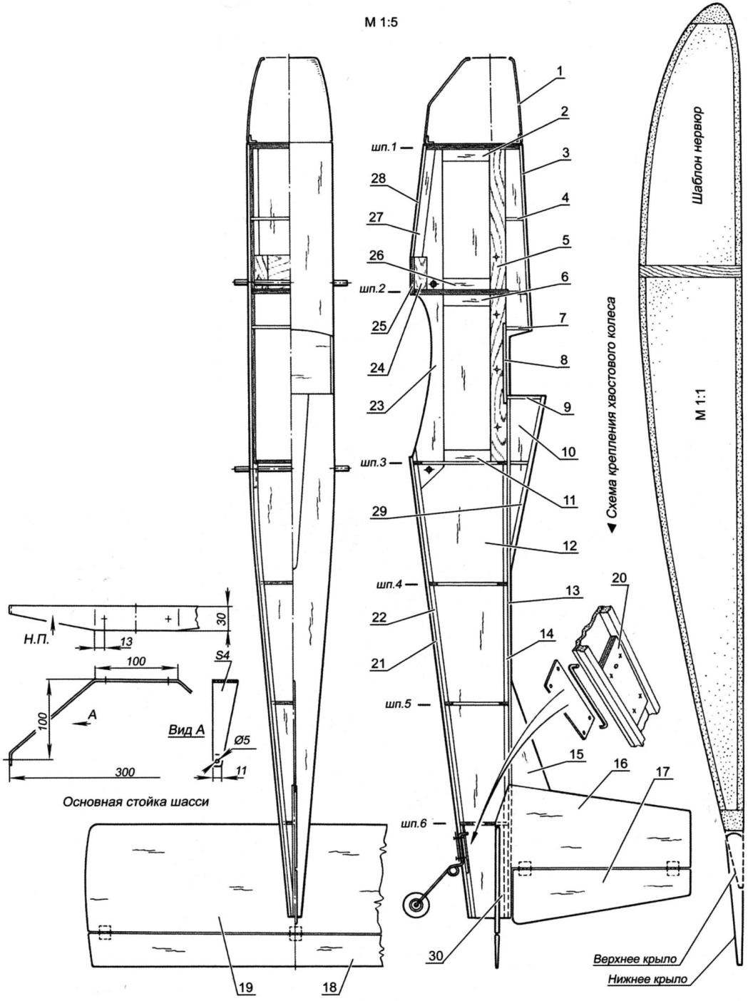
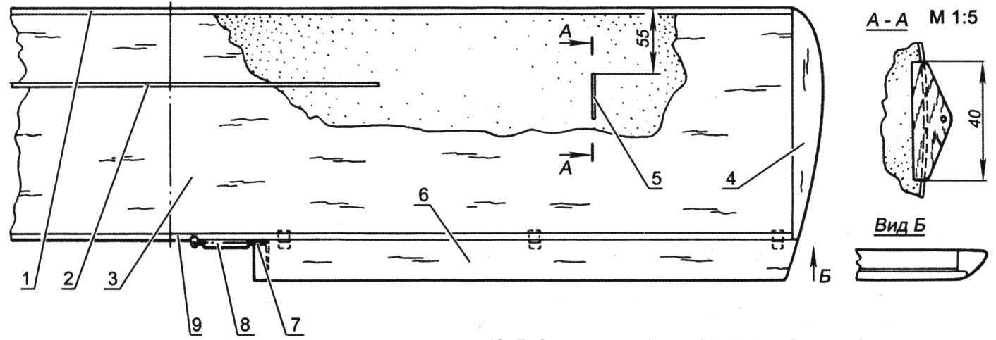
The fuselage. Front under engine frame 1 berekley sawn from plywood with thickness of 6 mm and 1.2 mm. the Frame II is made of plywood of 3+1.2 mm. the Rest of the frames are made of plywood with thickness of 3 mm. Side, bottom and top of the fuselage behind the cockpit from balsa 3 mm plates. Pidkaminna the semicircular fairing is typed on the finished frame of the fuselage of a separate balsa strips 3 mm thick (if desired, the middle portion of the fairing having a relatively small curvature, can be made of a single bent plate of balsa, and narrow strips to use just the edges). At the bottom of the fuselage from the inside put the lining of 3 mm balsa behind the rear edge of the lower wing. At the top, from the inside, the fuselage is reinforced with a strip of 3 mm plywood. In the corners of the tail are balsa rails with a cross section of 5×5 mm. In place of fastening of racks of the chassis bottom balsa sheathing replaced with 4 mm plywood and glued from the inside bars of hard wood of section 20×20 mm. they drilled the holes for the screws of the rack mount chassis. Rubber rings for attaching the lower wing to the fuselage glued wooden pins with a diameter of 7-8 mm. In the rear, in place of bonding of the stabilizer from the inside to strengthen further glued the strips of balsa with a cross section of 5×5 mm and a length of 90 mm. Before assembling the lower balsa skin of the forward fuselage in the front compartment invested wrapped in a sheet foam fuel tank with a capacity of 250 cm3. Underneath it useful to put the foam block, which then will not allow Baku to change the height position (later compartment of the tank will be unavailable). The canopy is cut from a plastic bottle.
Fuselage:
1 – the hood (fiberglass); 2 – pad (balsa s3); 3 – nose fairing (balsa s3); 4 – prosperous (balsa s3); 5 – force plate (plywood s3); 6 – plate (balsa s3); 7 – prosperous (balsa s3); 8 – polik cockpit (balsa s3); 9 – frame fairing (balsa s3); 10 – the skin of the fairing (balsa s3); 11 – trim (balsa s3); 12 – Board (balsa s3); 13 – upper trim panel (balsa s3); 14 – stringer (balsa 5×5); 15 – dorsal fin (balsa s3); 16 – keel (balsa s5); 17 – of the rudder (balsa s5); 18 – the Elevator (balsa s5); 19 – stabilizer (balsa s5); 20—pad rear landing gear (plywood s3); 21 – lower tail trim panel (balsa s3); 22 – stringer (balsa 5×5); 23 – reinforcement strip (balsa s3); 24 – bar of the rack mount chassis (beech, birch or solid pine 15×20); 25 – base plate (plywood s3); 26 – pad (balsa s3); 27 – stringer (balsa 10×10); 28 – front lower trim panel (balsa s3); 29 – upper panel fairing (balsa 16×5); 30 – strengthening the boards (balsa 5×5)
Material frame 1 – plywood plywood – s6 and s1,2 mm; bulkhead 2 – s3 and s1,2 mm; other – plywood, s3 mm in a single layer
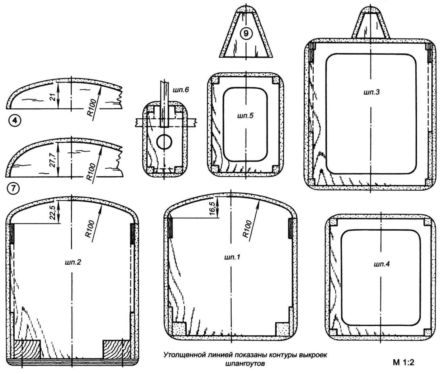
The frames of the fuselage.
The numbers of frames and parts conform to drawing of the fuselage. All the faces round the R8, as shown in figure
Unusual design stands the top of the wing for maximum comfort repair. All rack and Logement details parklea sawn from two layers of plywood with a thickness of 1.2 mm. Connecting cross rods diameter 7 – 8 mm made of solid wood. For fixing the screws came from broken cassettes. To prevent cracking of the ends of the rods, their ends are reinforced with threads wound coil to a coil and impregnated with glue. The fuselage struts are attached with self-drilling screws.
The tail Assembly. All items are carved from balsa 5 mm plates. The thickness of the rudders is reduced to the rear edges up to 2 mm. Hinge the rudders – on nylon (or rather, polyamide) hinges Termik. The rest of the elements – horns, threaded clevises of “Termika”.
Chassis. Front spring type bent out of aluminum. It should be noted that in the initial version, the plate thickness was 3 mm. But already during the first runs it was found that during flight the mass of the model is around 3 kg it is frequently unbent at landings. In the result, the strut was replaced on the thicker up to 4 mm. been Replaced and the wheels. Installed first “quilted” with a diameter of 60 mm was bad on the ground in the event of an unplanned rolling out of the way. Therefore, after a trial test model was delivered wheels “Thermals” with a diameter of 82 mm, which led to the improvement of the operation of the landing gear in all respects. Cabinets are now softer due to the increased “intensity” of the wheels, and also have the opportunity to take off and land on unpaved fields. The rear wheel with a diameter of 30 mm are supplied on an unmanaged stand of wire, allied with a diameter of 2 mm. it is Recommended to keep the approximate proportions of the rear rack shown in the drawings. This will provide a landing with sufficient attenuation of the tail model.
Wings. Console carved termolabil of polystyrene foam packaging type (you can use construction) and covered the balsa with veneer thickness of 1.5 mm. After Assembly of the parts into a single wings, they are reinforced by longitudinal wall, made of pine plates 3 mm thick As seen in the drawing, the spar occupies a third of the wingspan and its mounting have been applied the following technology: in a circular wood processing machine the disk mill 3 mm thick propylene through the groove to the desired length on the scale; in the groove sealed with plate-spar. On the lower wing due to the presence of V-shaped blank plate-side rail height is cut with a margin over ostrugivajutsja after gluing in place in the wing.
A typical actuator of the ailerons are presented torsion axles made of steel wire with a diameter of 2 mm, which are conducted through plastic bushings (the pieces of the empty rod from a ball pen). These pipes are wrapped with cotton thread and glued to the rear edge of the center of the lower wing. The top wing mechanization has not. To prevent podmyatiya balsa from the action of the rubber rings on the segments edge glued pine slats.
Wing:
1 – edge (balsa 12×5); 2 – spar (pine 25×3); 3 – upholstery (balsa 1,5); 4 – ending (balsa); 5 – eyelet (plywood 2); 6 – Aileron (balsa 35×4); 7 – axis of the Aileron (wire OVS 2); 8 – pad (pine 4×4); 9 – edge (balsa 6×5)
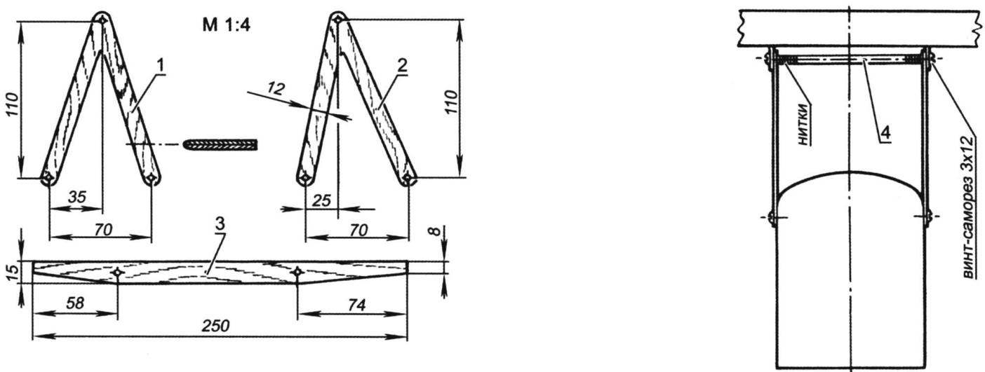
The Central strut of the wing:
1 – front fork; 2 – rear fork; 3 – cradle (parts 1,2 and 3 parklea cut from two layers of plywood 1,2); 4 – spacer (beech, diameter 7-8, length: 100)
On the right shows a rack together with the wing on the fuselage. Wing mount – a rubber band. The lower wing not shown
Front and rear edges of the wings from balsa strips. Ending visquine balsa sticks. Covering a classic (for models with a completely rigid covering) – mcalenney of paper pasted on a two-component parquet lacquer. Currently, the availability of modern plastic films gives a wide choice to use them instead of mcalenney paper. Savings in the complexity of gluing and painting is obvious.
On consoles wings applied adjustable racks from steel spokes with a diameter of 2 mm. At the ends of the struts is threaded for a screw-on tips (like pull). The design is simple but effective. During an emergency landing nodes’re disengaging easily without damage, and flight keeping more than reliable.
Management. Thrust to the height of the handlebars and turning made of round pine strips with a diameter of 6-7 mm. Ending segments formed pull steel spokes with a diameter of 2 mm and length 70 mm with threaded ends for screw-on nylon ferrules-forks.
All control equipment is mounted in a compartment above the lower wing. Involved four proportional channel (Elevator, rudder, ailerons and the carburetor of the engine). First servo that controls the ailerons were installed in the fuselage, but later it was transferred directly to the wing and secured it with mounting tape. The receiver is wrapped in foam and mounting tape glued to the frame 2. The battery pack is similarly attached to the “Polycom” of the cockpit. Block-Board servos are located in the Central part of the compartment. The model is applied to Japanese equipment “JR”.
Rotor group. On the model of the installed domestic hot surface motor MDS-6,5 KU with the standard muffler. Nylon propeller company “Thermals” with a diameter of 298 mm and a step of 130 mm has been cut to the size 270×130 mm. Possible to use any of the domestic and imported engines working volume of 5 to 8 cm3. At replacement it is necessary to consider the mass of the plant to maintain the correct alignment model. For the model with the engine “rainbow-7” or OS MAX 40 LA (and similar weight) can be recommended to increase the length of the forward fuselage for 30 – 35mm or to lighten the tail. Vegas the axis of the engine down to about 4°, to the right to 2°. The engine is mounted on a plastic or aluminum Motorama. The very same motor mount fixed to the front bulkhead with screws or self-tapping screws. The corners of Vicosa are governed by the wedge-shaped plates made of polystyrene.
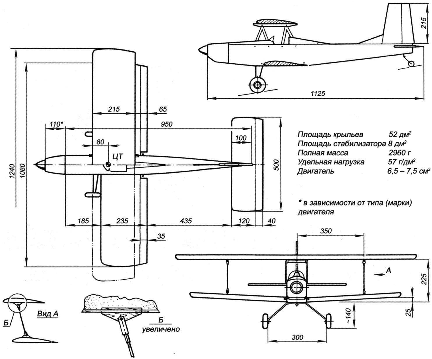
Balancing. The centre of gravity position indicated in the drawing. A more rearward position of the alignment makes the model very sensitive to the Elevator. The installation angles of the wings is zero. Deflection of the rudders height ±20°, rotation ±30°, ailerons – ±20°. On the first flight the angles of deflection of the ailerons it is recommended to set within ±15°, but after mastering the flight characteristics of the model to produce a corrective adjustment. In flight, the biplane behaves predictably and is stable, the management is quite responsive. On takeoff and landing model is no different from the classic. Due to the significant wing area, the model stable, even on polegate as in level flight and turn. PLANO profile makes it difficult to follow complex and reverse maneuvers. So the flight on the back of a barrel and reverse a half-loop well can be performed only by experienced pilots. But this is not a disadvantage of the biplane so as to monoplanes with wing like profile characterized by the same disadvantages. To obtain improved handling characteristics may be advisable to replace the profile of the wings symmetrical with a relative thickness of up to 15%.
A. GRISHENKO, V. KIBETS
Recommend to read
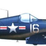 F4U CORSAIR – TEN YEARS IN THE SERIES
Fighter F4U Corsair the Chance Vought company refers to those aircraft that forever left a mark in the history of world aviation. The involvement of these aircraft in the air battles... FROM AN AUTOMOBILE – TRUCK
Increased interest motorists to cargo trailers is quite understandable. Still, the device is able of the car, indispensable for any economy, and primarily to rural residents and...
