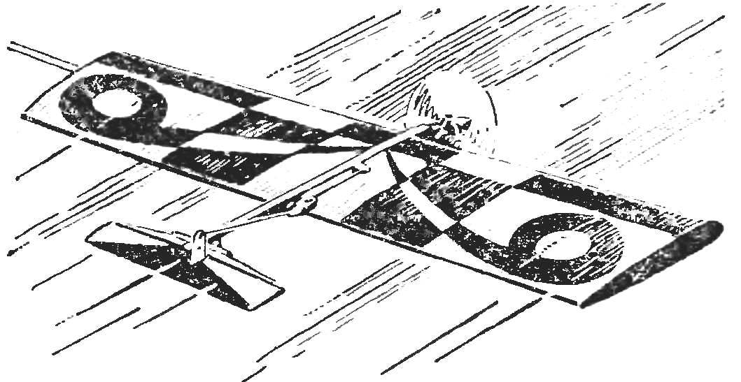
Truly consistently popular models class F2D. The possibilities of creative search is far from exhausted, and that no season, designers offer new solutions. An example is the model developed in aeromodelling lab at Home technical creativity of youth, acting at the black sea shipbuilding plant in Nikolaev. Modern scheme (the wing with the recommendations in the ravine tail plane rudder) processed under readily available materials, and high performance characteristics, vitality and great adaptability Assembly and repair had been preserved. Speaking with such equipment at the Republican youth games, a crew of young athletes DTM — Swiderski A. and S. Zhigunov — has become one of the winners of the competition.
Work on madalyn begins with the cutting head of foam stamps SS-BS-25 or SS-BS-30. Cutting is carried out using the jigsaw on the metal templates with polished edges. To finished items forehead on the PVA glue mate front edge and both shelves of the spar. PVA glue ensures a clean joint, and residual elasticity gives the device a greater resistance to shock loads. But to apply it in all compounds is impossible. For example, the end ribs must be installed on the epoxy resin, otherwise after a short time they “crawl” on the frame to the center of the wing under tension Mylar film covering.
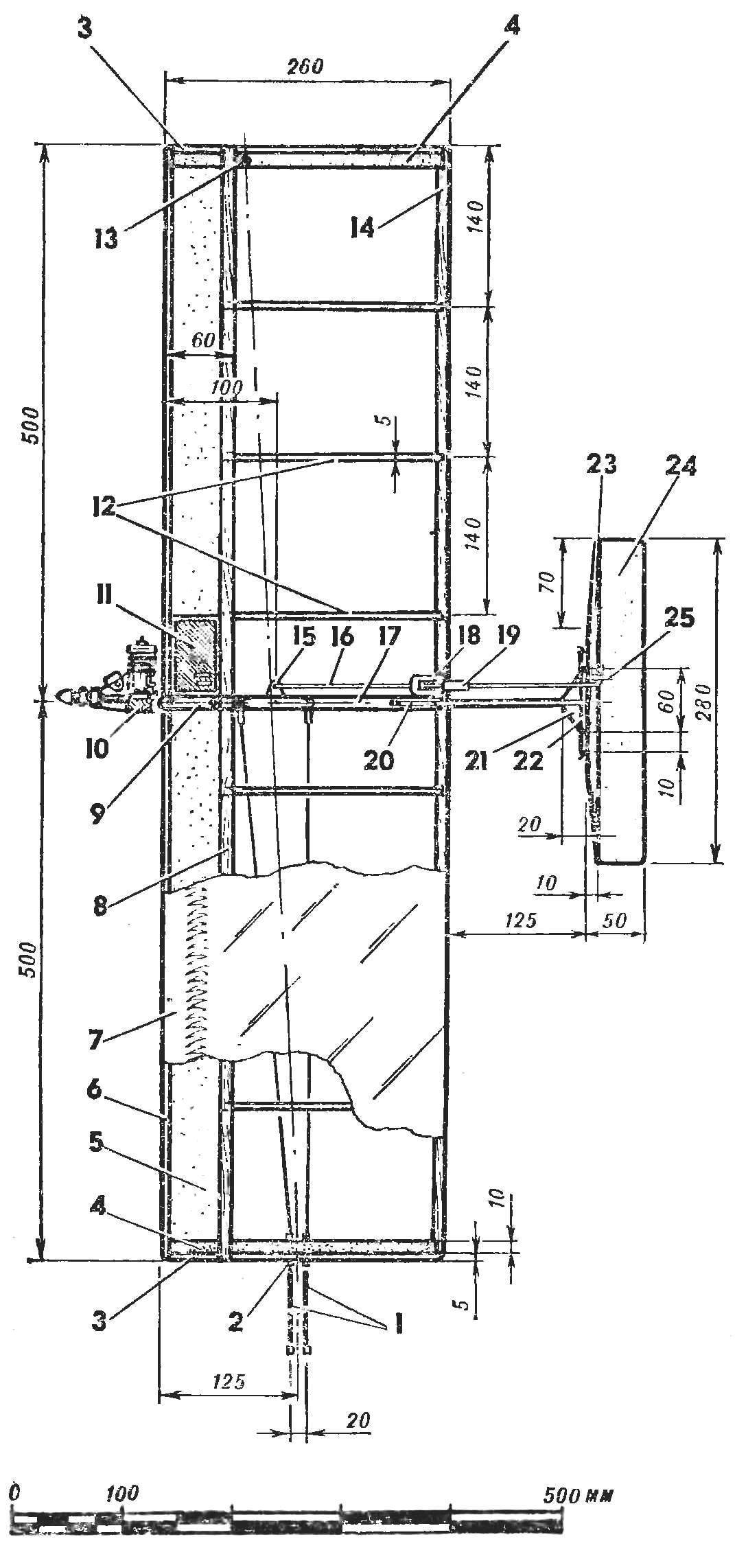
Fig. 1. – Control line model aircraft for air combat :
1 — wire control, 2 — tube wiring cables, 3 — the end rib, 4 — rib additional, 5 — foam forehead of the wing, 6 — the leading edge, 7 — Mylar film covering, 8 — shelf of the spar. 9 — front part of the Central rib, 10 — motor, 11 — fuel tank. 12 — rib, 13 — download of an external console (10 g), 14 — back edge 15 of the bellcrank control 16 — pull. 17 rear part of the Central rib, 18 — “ear” wire thrust through the wing, 19 — threaded coupler, 20 — tail ravine, 21 — hallstaberget, 22 — tube linkage of the Elevator, 23 — spar helm, 24 — handlebar height 25 the pig.
By the time of Assembly of the longitudinal frame wing to the forehead is useful to have a ready Central rib composed of a reinforced anterior (lime) and light (balsa) pieces. Harvesting rib joined on the epoxy, as this seam have the greatest impact and flight loads. After the installation of the Central rib to complete Assembly of the main frame of the wing by installing the fake rear edge and the remaining ribs. Intermediate cut from balsa wood with a thickness of 5 mm (the flying quality of the model almost does not lose, substitute them with lime 2.5 mm thick or plywood polutorametrovy). End ribs reinforce against flexure by gluing layers of foam PVC 2 thickness of 10 mm.
Fig. 2. The design of the power part of the model :
1 — motor, 2 — threaded pipe mount engine mounts (steel, gluing in children. 4 epoxy resin), 3 — M3 screw with split washer, 4 — the front part of the Central rib (lip thickness 10 mm), 5 — spindle rocking chair (steel tube d 3 mm), 6 rocking control 7 — rear part of the Central rib (thick balsa thickness of 10 mm, glue with children. 4 epoxy resin) 8 — M3 screws mounting ball glasses (gluing in children. 7), 9 — threaded coupler length adjustment rod (steel tube with an inner pain” fight M3). 10 — pull steering (wire of aluminum alloy AMG d 3 mm). 11— tail ravine (dural tube d 7-8). 12 — polystability-tor (plywood 3 mm). 13 — hog steering
It is now for installation in a reinforced part of the Central rib of two steel tubes of 4 mm outer d and internal threads M3. They are carefully degreased and glued epoxy. Subsequently, these “nests” are rolled steel screws fixing the motor. Carved from three similar tube — extra will go on the threaded clutch thrust of the Elevator.
Fig. 3. Wing section :
1 — the front edge (lip section 5X13 mm). 2 — forehead, wings (light foam), 3 — beam flange (lip section of 3X7 mm), 4 — rib (balsa average thickness of 5 mm), 5 — rear flange (lip section 5X13 mm) on the forehead of the wing dotted line shows the location of the fuel tank from the Central rib.
In the hole at the back of the Central rib saliva is axle mounted rocker control. The axle — tube in its channel is a cable connection rocking with the engine mount (this is dictated by the competition rules to improve safety). Thrust rudder is bent from aluminum wire. She transient through the plywood sheathing through the “eye” at the end of the thrust threaded M3. Navertyvanija on the steel shank coupling not only allows to adjust the pushrod length when adjusting the neutral position of the Elevator, but also facilitates attikovu tail beams during transport and repair model.
Remains to stick in the shank of the Central ribs of the two screws of the hinges of the beams, set in the right rib of the external balance weight and mount the ropes of the swing with their guides. The training wing to the tight ends.
Fig. 3 Rocking control
Detachable tail ravine — the tube D16T external ø 7 — 8 mm. of Its rear end cut, and the cut mounted miniature plywood hallstaberget whose sole job is to carry the tube serier hinge of the Elevator. As the presence of a hinge and mate glued to the steering wheel, made of aluminum foil with a thickness of 0.5 mm. Axle steering pozolota — wire AMG d 2 mm. the Elevator Assembly consists of a power lime of the spar cross-section of 4X10 mm and podstekolnoj tail from foam PCV-2. External finish: plane ready helm is covered by two layers of parquet lacquer, the Horn is cut from a double layer parklea mm or polutorametrovoy plywood and epoxy is installed in slot helm. You must strive to ensure that the basic length of the slot had CA foam, otherwise the rail-spar helm may be too weak. Ready-made plumage is mounted on the screws of the Central rib of the wing. When the control Assembly into the rib hollows out a shallow groove up the ravine to the Elevator was on brozne wing. However, this can be achieved by tightening the screws on an already covered model. Film and balsa under the beam a little deformidade, but it will be a possibility of impregnating the balsa with fuel.
Fig. 5. Hog (switching from two layers of mm or polutorametrovoy plywood) .
Shaded plot of the pylon is glued in the slots of the stabilizer.
Engine — glow CSTAM 2,5 K — mounted on the fender with the two halves of the engine mounts, milled from alloy AMG. Experience of operating such models have shown that this material is preferable D16T or-95: engine mount made of aluminium alloy has a high “survivability”. EV half exactly the same, it is sometimes closet the competition when building models from multiple broken. Fuel tank, single chamber, working pressure bleed using the standard fitting of the rear wall of the engine crankcase. Tank volume of about 90 cm3 soldered tin with a thickness of 0.25 mm and fixed in a recess of the forehead, wing sticky tape in front of the slinky model of Mylar film. This simplifies the replacement of the tank. As the need arises on contests quite often. Cut out the section of the Dacron covering the recess of the forehead, to replace the tank and re-tighten the wing for the cut contour.
Fig. 6. Fuel tank :
1 — housing (lsast tin or thin sheet brass), 2 — tube power engine, 3 — tube drainage or over-d>tva cavity tank pressure taken from the crankcase of the engine.
Such a solution allows for departures to the competition to complete ten models are only 5-6 tanks. Undoubtedly, cutting niches in the foam weakens the otherwise closed circuit of the power frame of the wing. But two years of prantika flight showed that failure of the wing in place of weakening under the tank are only a third of all the others. High properties characteristic of interchangeability and for construction in General from a few broken in “combat” you just collect new.
Fig. 7. Motor mount (aluminium alloy AMG)
Alignment is a fully equipped model — 60 mm from the leading edge. The position of the center of gravity lengo to pick up, shifting the engine with the engine mount in the elongated slots of the shanks of the motor.
P. SWIDERSKI, group leader of the laboratory DTTM, Nikolaev
Recommend to read EKRANOPLAN “LUN” In 1987, the water came down, "LUN" the first ship of the series of combat missile-carrying wig weighing 400 tons was the Chief designer V. Kirillov was. The ship was armed with three... DRILL WITH RADIATOR Modern engineering makes high demands on the materials, and they, in turn, to the machining tools. Not by chance all the exhibitions NTTM necessarily demonstrates the new development of... 
 Truly consistently popular models class F2D. The possibilities of creative search is far from exhausted, and that no season, designers offer new solutions. An example is the model developed in aeromodelling lab at Home technical creativity of youth, acting at the black sea shipbuilding plant in Nikolaev. Modern scheme (the wing with the recommendations in the ravine tail plane rudder) processed under readily available materials, and high performance characteristics, vitality and great adaptability Assembly and repair had been preserved. Speaking with such equipment at the Republican youth games, a crew of young athletes DTM — Swiderski A. and S. Zhigunov — has become one of the winners of the competition.